3
- F -
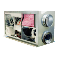
1. Trappe d’inspection 8. Gaine d‘extraction de la hotte, si installée (d. 125,
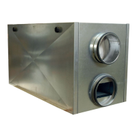
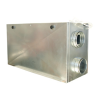
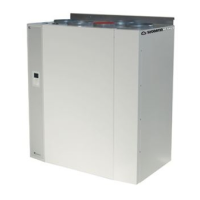
VR400
2. Silencieux DCV/B)
4. Prise d’air neuf 9. Gaine souple
5. Refoulement du rejet 10. Gaine rigide
6. Diffuseurs 11. Isolation de gaine, voir chapitre dédié
7. Bouches d‘extraction 12. Gaine d‘air neuf vers la grile extérieure
13. Plaque de jonction centrale – plafond, si nécessaire
Attention ! L‘unité VR 400 DCV/B est disponible en version droite ou gauche selon le besoin.
Attention ! Installation du support de montage mural (1): le support se situe 45 mm au dessus
du haut de l‘unité une fois fixé au mur. Vérifier que la barre anti-vibration et que
l‘arrière de l‘unité ne soient pas endommagés lors du montage. Soulever l‘unité pour
la mettre en position et assurez vous qu‘il n‘y ai pas contact entre l‘unité et le mur.
1. Inspection hatch 8. Duct from cookerhood, if installed (Ø125/ VR 400 DCV/B)
2. Sound attenuators inlet/extract 9. Flexible ducting
4. Fresh air intake 10. Spiro ducting
5. Discharge extract air 11. Condensation-/ heat insulation, see
6. Air inlet/inlet diffusers separate chapter
7. Extract/extract louvers 12. Grade towards wall grill
13. Duct cover between roof and unit, if required
NOTE! VR 400 DCV/B is available both as a right and left hand model.
NOTE!Install mounting bracket (1) on the wall. Bottom side of bracket should be 45 mm below top of
unit position, when installed on the wall. Check that the anti vibration packing (2) on the
mounting bracket and on the backside of the unit (3) is undamaged. Lift the unit into position
and make sure that there is no direct contact between unit and building construction.
Fig. 1
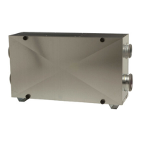
4xØ160 mm
1xØ125 mm (8)
4xØ200 mm
VR 400 DVC/B L (version gauche)
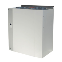
VR 700 DVC