Systematics , Inc. 1025 Saunders Lane West Chester, PA. 19380 9
PROCESS SELECTION (Cont.)
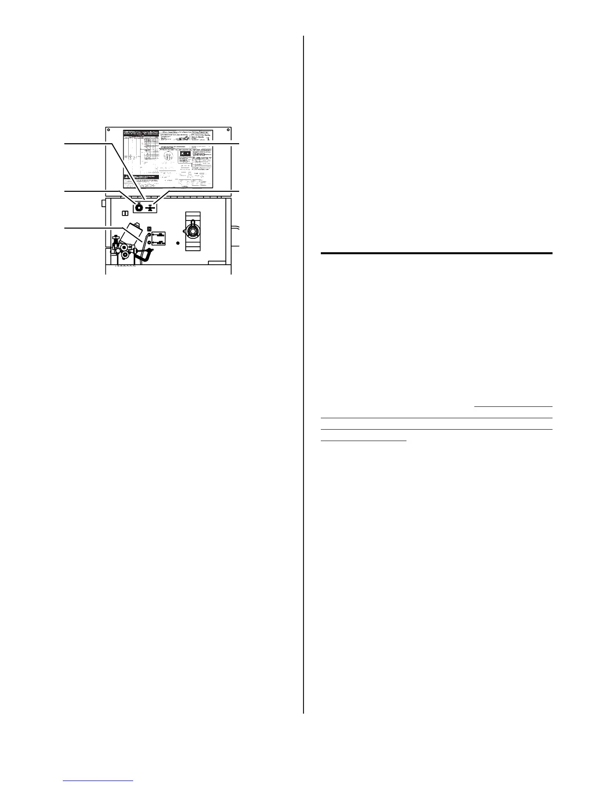
The following controls are lo-
cated on the inside of the machine,
in the wire feed compartment.
E. *FUNCTION SWITCH
Controls mode of operation of
welding machine. "CONT. WELD"
position is for normal, con-
tinuous welding operation.
"SPOT" position puts the spot
timer in the circuit for auto-
matic MIG Consumable Spot Weld-
ing. "STITCH" position is used
for stitch welding on very
light material. When in
"STITCH" position, the length
of time the welder is "ON" and
feeding wire is controlled by
the Spot Timer. The lower the
Spot Timer setting, the faster
the welder cycles on and off.
A.
*OPTIONAL
SSTP-2
MODULE
B.
*SPOT
TIMER
C.
SELECTOR
HOSE
D.
PARAMETER
CHART
E.
*FUNCTION
SWITCH
WELDING
Optimum control settings will
vary according to the thickness of
the metal, the type of joint,
operator preference, etc. Best
results can be obtained through
experience with the welding ma-
chine or by making trial welds.
Select some sample material of the
same type and thickness as the
material to be welded. Refer to the
Parameter Chart located on the
access door to the wire feed
compartment. Set the welding
controls for optimum results using
the sample material thickness and
wire size being used as a starting
point, weld until experience is
gained using the unit.
CONTINUOUS WELDING ON STEEL
1. Trim the electrode wire to
leave approximately 1/4 inch
stickout beyond the end of the
contact tip and install the
welding nozzle. The contact tip
should be flush or stick out up
to 1/16 inch beyond the end of
the nozzle.
A. *OPTIONAL SSTP-2 MODULE
With the optional Spot/Stitch
Module installed MIG Spot weld-
ing and Stitch welding can be
performed.
B. *SPOT/STITCH TIMER
After the torch trigger is
actuated, the timer allows the
wire to feed and the gas and
power to flow for the time
selected. The Function Switch
must be set in the "SPOT"
position (or the "STITCH" posi-
tion for stitch welding).
C. SELECTOR HOSE
Attaches to MIG position for
Standard welding through the
MIG torch assembly or to MHG7
position for Aluminum welding
with the spool gun option.
D. PARAMETER CHART
This chart is a guide for basic
setup parameters.
(continued on following page)
FIGURE 9. WIRE FEED COMPARTMENT