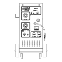
Systematics , Inc. 1025 Saunders Lane West Chester, PA. 19380 19
WIRE FEED CALIBRATION
Due to INPUT LINE VOLTAGE varia-
tions supplied to the welding
machine. The WIRE FEED SPEED should
be checked for proper operation.
TO CHECK
1) Remove any tension on the drive
roll.
2) Turn the wire speed dial (on the
front of the machine) to "0".
3) Activate the torch trigger.
4) The bottom drive roll should
rotate very slowly(non-jerky).
5) If this proves to be true, no
adjustment is required.
IF ADJUSTMENT IS REQUIRED
1) Remove the top cover assembly
from the unit.
2) Locate the printed circuit
board(s).
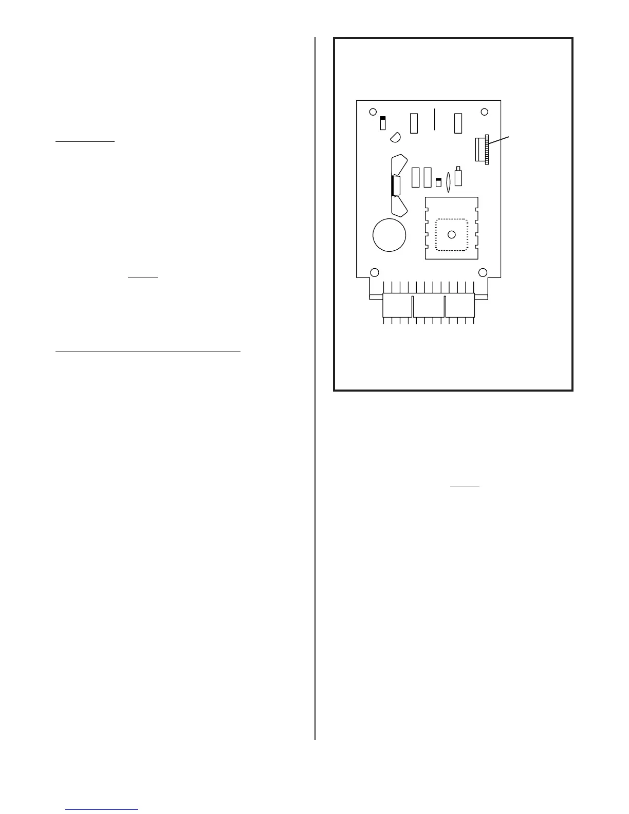
3) Referring to Figure 17, locate
the trim resistor, this is
located in the upper right hand
corner of the wire feed PC
board.
4) Turn the wire speed dial (on the
front of the machine) to "0".
5) Remove any tension on the drive
roll.
6) Activate the torch trigger.
7) Rotate the trim resistor, back
and forth, until the bottom
drive roll moves.
8) Calibrate so the bottom drive
roll rotates very slowly (non-
jerky).
9) If calibrated correctly the
wire speed dial (on the front of
the machine) should affect the
speed of the drive roll from "0"
thru "10".
10)Adjustment is now complete!
TRIM
RESISTOR
FIGURE 17. WIRE FEED PC BOARD