Systematics , Inc. 1025 Saunders Lane West Chester, PA. 19380 21
The MIG torch liner provided
with the MP140 is designed for wire
diameters from .035 thru .045. If
smaller wire diameters are to be
fed and or there is a problem (i.e.
clog, kink, etc.), a liner change
is required.
Following is a step by step
guide to aid in liner removal and
installation.
NOTE
When removing the welding wire
from the MIG torch, care should
be taken to avoid the wire from
uncoiling from the wire spool.
REMOVING OLD LINER
1. Remove torch assembly from the
welding machine.
2. Place torch assembly on a flat
surface, making sure torch is
laying straight as possible.
3. Remove nozzle, bushing insula-
tor, contact tip and gas dif-
fuser from the front end of the
torch assembly.
4. Loosen set screw located on the
connector end of the torch
assembly (see fig. 20).
5. Grip the liner and gas seal
firmly, then pull. The liner
should easily slide from the
torch assembly.
INSTALLING NEW LINER
1. Remove the new liner from the
package.
2. Uncoil liner and lay the liner
parallel next to the MIG torch
assembly.
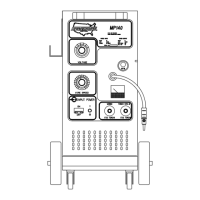
3. Adjust the liner stickout length
to 3/4" as shown in fig. 19.
3/4"
LINER
STICKOUT
GAS SEAL
SET SCREW
3/4"
CONNECTOR
PLUG
1 1/4+"
PROTRUDING
LINER
NECK
ASSEMBLY
4. Install the new liner into the
MIG torch assembly, until gas
seal seats flush with the con-
nector plug.
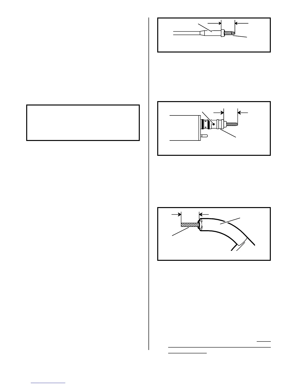
5. Tighten set screw. (Do not
overtighten), refer to fig. 20.
6. Following the diagram in fig.
21, measure out 1 1/4"+ from the
neck assembly and cut off the
protruding liner.
7. Debur the cutoff end of the
liner to insure unobstructed
wire feed.
8. Install the gas diffuser and
contact tip of proper wire
size, tighten with a wrench.
9. Install the bushing insulator
onto the gas diffuser. Spray
the "O" rings with anti-spatter
compound for lubrication.
10.Install the TWIST-ON adjust-
able nozzle and twist the nozzle
during the installation. Turn
to Page 6 for correct nozzle
adjustment.
FIGURE 21. TORCH FRONT END
FIGURE 20. TORCH CONNECTOR END
FIGURE 19. LINER STICKOUT
M.I.G. TORCH LINER
INSTALLATION
(steel only)