Do you have a question about the Taco PC702–1 and is the answer not in the manual?
Explains how heating systems match heat supplied to heat lost based on outdoor temp.
Combination of boiler starting temp and outdoor starting temp for reset ratio calculation.
Required water temp during the coldest day of the year for reset ratio calculation.
Heating system shuts down when outdoor temp is warmer than WWSD setting.
Boiler on/off cycling with a differential to prevent short cycling and improve efficiency.
Minimum supply water temp to prevent boiler corrosion from flue gas condensation.
Control overrides reset ratio for DHW demand, raising supply temp for DHW generation.
Control obtains boiler demand from Taco Zone Control when a zone calls for heat.
Control obtains DHW demand when voltage is applied across DHW demand wires.
Control displays WWSD segment and turns off boiler when outdoor temp rises above setting.
System supply water temp controlled by cycling boiler based on outdoor temp & reset ratio.
Control targets a supply water temperature of at least 180°F (83°C) for DHW demand.
Control does not allow boiler target temp to exceed design temp plus 10°F or 225°F max.
Setting selects minimum boiler target temp to prevent corrosion from flue gas condensation.
Optional boiler rotation function fixed at 48 hours to equalize stage running time.
Control manages two stages using interstage delay and PID logic for target temperature supply.
Sets minimum time delay between first and second stage firing.
Check package contents, contact sales rep for missing or damaged items.
Instructions for mounting the control enclosure onto a 2" x 4" electrical box.
Mounting the outdoor sensor on a wall representing the building's heat load.
Strapping the boiler sensor to a pipe or placing in a temperature immersion well.
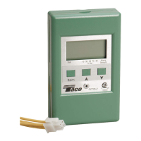
Connect PC702-1 cable to Taco Zone Control Add-On interface, set Mode switch to Reset.
Connect Outdoor Sensor to Com/Out terminals and Boiler Sensor to Com/Sup terminals.
Stage 1 & 2 terminals are isolated outputs used as switches to control boiler circuits.
Apply voltage to DHW demand wires to generate a DHW demand.
Sets the starting supply water temperature for the reset ratio, adjustable 35-150°F.
Outdoor temp at which starting temp is supplied, adjustable 35-85°F.
Water temp required for building heat loss at coldest outdoor temp.
Outdoor temp used in heat loss calculation, set to typical coldest outdoor temp.
Minimum operating temp to prevent boiler corrosion from flue gas condensation.
Sets how far supply temp may deviate before boiler turns on/off, can be Auto or 2-42°F.
Sets minimum time delay between first and second stage firing, 30s to 4 min.
Boiler shuts down when outdoor temp is warmer than setting (35-100°F or Off).
Enter adjustment mode by pressing and holding Item, A, and V buttons simultaneously.
Control displays segments, version, then outdoor temp; view menu shows temperatures.
Identifies faults like outdoor/supply sensor errors or EEPROM faults and their effects.
Tips for adjusting settings based on room comfort and boiler cycling issues.
Procedure for testing sensor resistance using a meter and comparing to a chart.
Secure wiring cover, place front cover, and explain operation to end user.
Displays error messages for EEPROM, Outdoor Sensor, and Boiler Sensor faults.
Lists control specifications, dimensions, approvals, and environmental conditions.
The Taco PC702-1 is a microprocessor-based control designed to manage the supply water temperature in a two-stage boiler system. Its primary function is to regulate this temperature based on either the outdoor temperature or the demand for domestic hot water (DHW). The control comes with a wiring harness for easy connection to Taco Expandable (-EXP) Controls.
The PC702-1 employs an "outdoor reset" strategy to optimize heating system performance. This strategy ensures that the heat supplied to a building matches the heat lost from it. The control modulates the supply water temperature as outdoor temperatures change, leading to improved comfort and significant energy savings. By running the boiler(s) at cooler temperatures, the system becomes more efficient, reducing heat losses through the flue and from the boiler jacket.
A key feature is the "reset ratio" calculation, which determines how much the supply water temperature is adjusted for every 1° drop in outdoor air temperature. This ratio is established using two points: a "starting point" and "design conditions." The starting point combines an adjustable boiler starting water temperature and an outdoor starting temperature. The design conditions represent the required water temperature during the coldest day of the year.
The control also incorporates a "Warm Weather Shut Down (WWSD)" function. When the outdoor air temperature exceeds the WWSD setting, the heating system is shut down, as no additional heat is required. This feature contributes to energy savings but does not affect the reset ratio calculation.
For boiler operation, the PC702-1 manages the boiler(s) by cycling them on and off. It includes a "differential" setting to prevent short cycling. When the supply water temperature drops below the differential's bottom rail, the boiler turns on and stays on until the temperature rises above the top rail. The control can automatically calculate this differential to balance temperature swings and boiler efficiency, adapting to changing loads and conditions.
A "minimum boiler supply" setting is included to prevent corrosion from flue gas condensation, ensuring the boiler operates at or above its manufacturer's recommended minimum temperature. For condensing and electric boilers, this setting can be turned off.
In cases of DHW demand, the PC702-1 overrides the reset ratio and raises the system supply temperature to a level suitable for DHW generation, typically at least 180°F (83°C).
The control supports up to two stages of boiler operation. After the first stage activates, there's an "interstage delay" before the next stage can fire. This delay is adjustable and helps manage the boiler's response. The PC702-1 uses Proportional, Integral, and Derivative (PID) logic to determine when to activate the next stage. Proportional logic compares actual to target supply temperature, integral logic considers this over time, and derivative logic assesses the rate of temperature change.
An optional "boiler rotation" function is available, fixed at 48 hours. This function ensures that both boiler stages receive equal running time by changing the firing order whenever one stage accumulates 48 hours more running time than the other. If boiler rotation is off, Stage 1 always fires first.
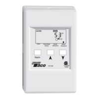
The PC702-1 features a digital Liquid Crystal Display (LCD) that typically shows the Boiler Supply temperature but can also display other temperatures and settings.
To adjust settings, users simultaneously press and hold the "Item," "A," and "V" buttons to enter the adjustment mode, indicated by the "ADJUST" element turning on. From there, the "Item" button is used to cycle through various settings, and the "A" and "V" buttons adjust the values. Settings include:
The control automatically saves all settings and reverts to viewing mode if buttons are left untouched for 20 seconds.
The PC702-1 includes error messages displayed on the LCD to indicate the location of a problem, simplifying troubleshooting. These messages include:
In case of an outdoor sensor fault, the control assumes a fixed outdoor temperature of 32°F (0°C) and targets an appropriate supply water temperature. A supply sensor fault turns the boiler off. An EEPROM fault turns the boilers off until all settings are checked.
For troubleshooting, users are advised to isolate the problem, identify the fault from the error messages, and follow standard testing procedures. If a wiring fault is suspected, external wiring and connections should be carefully checked.
The manual provides guidance on adjusting settings to address common issues:
Sensors can be tested by measuring their resistance using a quality test meter (capable of measuring up to 5,000 KΩ). The actual temperature should be measured with a digital thermometer, and the sensor resistance reading should correspond to the provided resistance-temperature chart. Discrepancies (very high or very low resistance) can indicate a broken wire, poor connection, moisture, or a defective sensor. It is crucial not to apply voltage to a sensor during testing, as this can cause damage.
| Category | Controller |
|---|---|
| Input Voltage | 24 VAC |
| Housing Material | Plastic |
| Model | PC702-1 |
| Weight | 0.2 lbs |