2
9. Check run-out on bowl shaft extensions by placing dial indi-
cator toward the end of the shaft and turning slowly making
certain the shaft stays to one side of the upper most bowl
bearing. Total Indicating Run-Out should not exceed .005”.
10. Check and record the total bowl lateral or end play. If a
solid shaft motor is used, this information will be required for
flanged coupling assembly.
A5: INSTALLATION INSTRUCTIONS
A5.1: BASE PLATE OR FOUNDATION PLATE
(IF SUPPLIED)
1. Place foundation plate over anchor bolts and allow to rest on
foundation. Check to make sure foundation plate is level, use
wedges or shim stock if necessary. Full contact with founda-
tion is important for vibration free operation.
2. If the final elevation of the plate is critical, this should be
checked at this time.
3. Attach hex nuts to anchor bolts and turn until snug against
foundation plate.
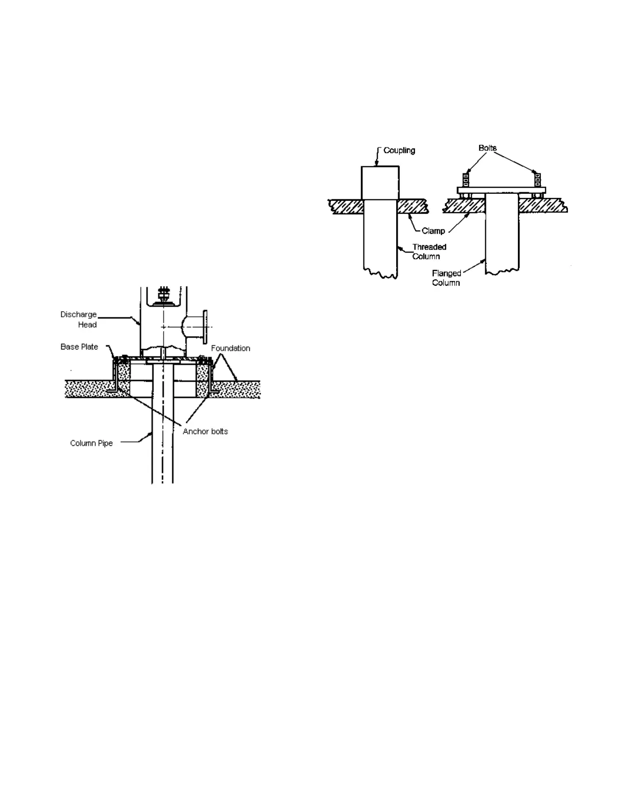
4. The foundation plate serves as a good surface for the dis-
charge head. See Figure A5.1.
A5.2: PUMP BOWL
1. Place the two beams on the foundation plate or foundation
opening.
2. Secure the proper clamp to the upper end of the bowl beneath
a convenient shoulder. If only one sling is used, attach the
sling to the clamps far enough out on the ears to allow for easy
removal after setting the unit down on the beams.
3. Hoist the bowl to a vertical position using the derrick. If the
bowl is equipped with a strainer, do not drag the strainer
across the floor.
4. If there is any auxiliary piping to the bowl bearing or the
thermo-wells, make certain the bowl portion of the piping is
attached to the bowl at this time.
5. Center the bowl over installation opening then carefully lower
until the clamp ears are resting squarely on the beams. Then
remove the sling.
6. Clean the following items: shaft threads, discharge threads,
flange face (if applicable), threads and face of oil tubing (if
applicable). Lightly oil the shaft threads and screw the cou-
pling on half way. Place a rag over the coupling to prevent
entrance of foreign matter during the next step in assembly.
A5.3: COLUMN OPEN LINESHAFT
Refer to the installation plan or the overall dimension sheet
of the submittal to determine correct sequence for installation of
column lengths.
1. Secure pipe clamp immediately beneath column coupling.
If column is flanged, insert bolts and secure clamp below
bottom of flange. Clamp should keep bolts in position. See
Figure A5.3.1.
2. Slide the lineshaft into bottom of column pipe and allow it to
extend approximately 15” below the bottom end of the pipe.
Make certain the sleeve area of the lineshaft (if applicable)
is toward the top of the pipe. Tie a series of half hitches to
the column pipe and lineshaft with
3
⁄
4
” rope. (Tie the rope to
a chain pipe vise on the lineshaft, if needed.) Attach the sling
to the clamp ears as described under Section A5.2, Step 2.
3. Hoist column and lineshaft to a vertical position with the der-
rick. Do not drag shaft across the floor. Before centering col-
umn over bowl, tap the side of column to remove any loose
matter.
4. Position the column and lineshaft over the bowl. Align the
lineshaft and remove the rag from the bowlshaft coupling.
Lightly oil the threads. Lower until the lineshaft contacts cou-
pling. Remove the rope. Hold coupling and turn the lineshaft
(left hand threads) until the shaft ends butt up. Place one
pipe wrench on the coupling and one on the lineshaft. Tighten
securely. Remove the wrench marks form the shaft and cou-
pling with a flat file and emery cloth.
5.a If bowl to column connection is threaded, apply thread
compound to the pipe threads. Attach chain tongs to bowl
and to column for support. Lower the column pipe, and at
the same time, turn the pipe until it seats against the mating
shoulder on the bowl. Tighten pipe into bowl securely.
5.b If bowl to column connection is flanged, spread a thin,
even film of gasket compound on the bowl discharge flange.
Lower pipe and align studs in the bowl with the holes in the
flange. Seat the column flange against bowl flange. Install
and tighten hex nuts evenly.
6. Hoist assembly enough to remove the clamp on the bowl
assembly.
7. If there is any auxiliary piping to bowl bearing or thermo-well
being used, that portion that attaches to the column section
should now be installed. Also, if the bowl and column are
coated with any special coating, any required patch work
should be done before lowering unit.
8. Slide beams in close to column. Lower the assembly and rest
the clamp ears on the beams. Remove the sling.
Figure A5.1
Figure A5.3.1

 Loading...
