H-2 H-2
Boom Length/Angle Detector
19
W305-0490E
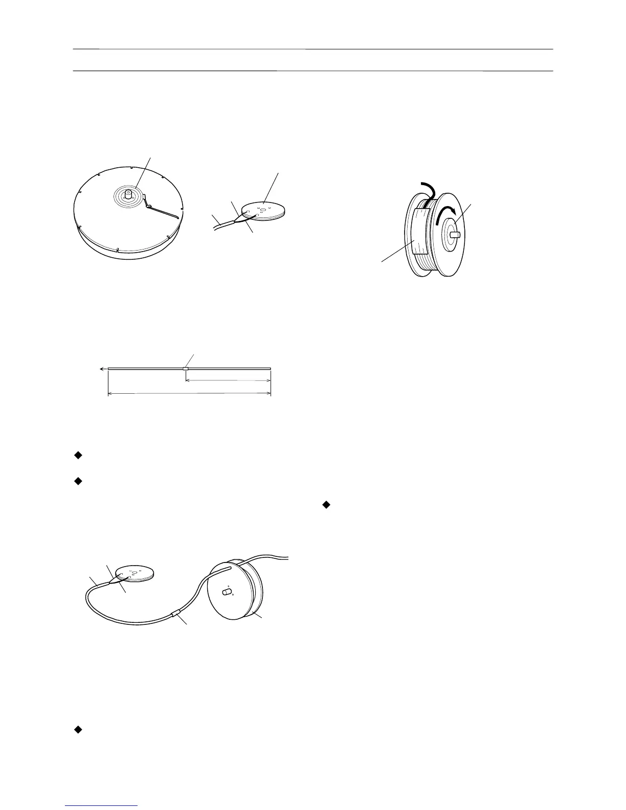
7. Remove the slip ring assembly from the drum
assembly. Then, remove the connection
(soldered) of the slip ring and cord.
IW305-0130E05
Cord
Core wire
Shield wire
Slip ring assembly
Slip ring assembly
8. Remove all the old cord from the drum assembly.
2.2 Reassembly of cord
1. Mark the new cord with yellow tape as shown.
To drum
Yellow tape
9700mm(31.82ft)
42170mm(138.35ft)
IW305-0490E02
[NOTICE]
Connect cord core wire to the inner slip ring.
Connect shield wire to the outer slip ring.
Completely insulate the soldered portions.
2. Pass new cord through holes of drum assembly.
Solder new cord to slip ring assembly in the
reverse procedure for disassembly.
IW305-0130E07
Core wire
Cord
Shield wire
Vinyl tube
Drum assembly
3. Install slip ring assembly while preventing slack
of cord.
[NOTICE]
Wind the cord around the drum assembly clockwise
as seen from the slip ring.
4. Wind new cord arround drum assembly while
preventing slack. After zero marker (at 7.0 m)
{22.97 ft} from the end of cord appears on drum,
wind cord 1 turn additionally and fix it with
gummed tape to prevent it from loosening.
IW305-0130E08
Gummed tape
Slip ring
5. Insert the shaft of the drum assembly into the
boss hole in the plate, and secure the shaft with
the nut .
6. Put case over drum assembly while passing
sub-cord through hole of case and cord through
opening of cord guide.
7. Secure the case and plate with the bolt, and install
the retaining ring.
8. Apply a thin coat of sealant over the bottom of the
reduction gear and install the reduction gear on
case.
[NOTICE]
If the potentiometer is faulty, refer to “Replacing
potentiometer (for boom length detection)”
described later and replace the potentiometer at
that point.
9. Set the gear on the shaft of the reduction gear
and loosen the set screw of the gear on the
potentiometer side to allow both gears to idle.
Turn the gear of the potentiometer about a 1/4
turn with your finger and confirm that the gear
returns to its original position by the force of the
spring. If not, loosen the bolt and adjust the
position of the bracket.
10. Fix the gear in the notched section of the shaft of
the reduction gear, using the set screw. Apply
screw-locking compound to the set screw.
Tightening torque: 118 N•cm {0.87ft•lbf}



 To Next Page