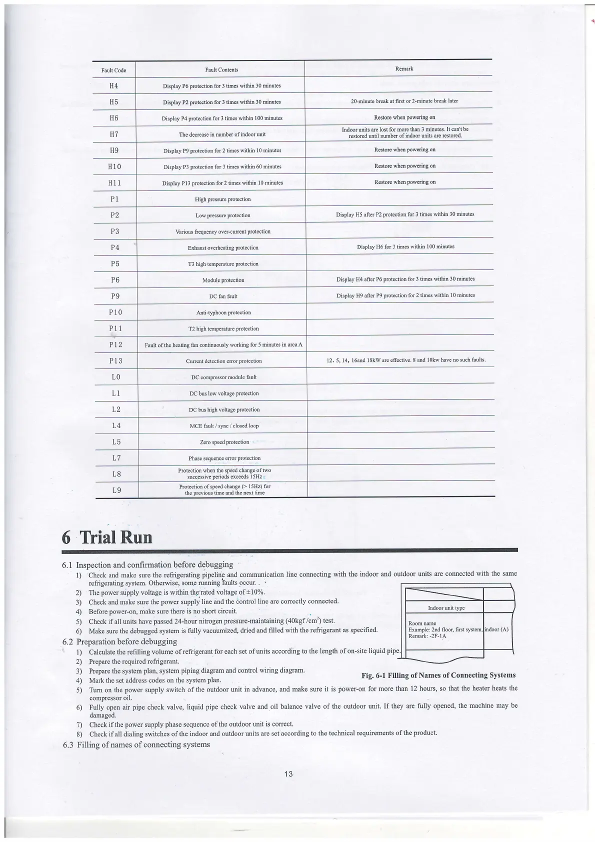
Fault Code
Fault
Contents
Remark
H4 Display
P6
protection for 3 times within 30
minules
H5
Display P2
Fotection
for 3 times within
30 minutes
z0{itrute
break at fi6t or
2-minute break
later
H6 Display
P4
protection for 3 times within
I
00
miniles
Restore
when
powenng
oo
H7
The decrease
in number ofitrdoot
uili1
Indoor units de
lost for mole
the 3 minutes. It cm't
be
restored until
nmrber of indoor units
arc restoted
H9 Display
P9
protoction tbr 2 times
within I 0 minutes
Restore when
powoing on
H10 Display P3
protection for 3
times within 60 mitrutes
Restore whd
powering
o0
H11 Display
PIJ
J'rotection
for 2 limes
within l0 rninutes
Restorc when
powering on
P1 Hi
gh piessure protection
P2 Low
presswe protection
Display H5
after P2
protection for 3 times wilhin
30 minttes
P3 Vanous
frequency over-crfr€ntproleclion
P4 Exhaust
overheating
protection
Display H6
for
3
times within I 00
hinutes
P5
T3 high tcmpcralurc
protection
P6
Module
protection
Display
H4 after P6
protection for 3 times
within 30 minutes
P9
DC far fault
Display
H9 after P9
protection for 2
times within 10 minutes
Pi0
Anti-t'?hoon
prolection
P11
T2 high
tenDerature
protection
Pt2 Fault of the heating
fm continuously
working for 5 mintcs
in area A
P13
Cwent
dctcction cror
protcctton 12.
5. 14, l6dd l8kw
de eflective. 8 and
l0kw have no such
faults
LO
DC comprcssor
module
fault
L1
DC
bus
low voltage
protection
L2
DC bu high voltage
prctection
L4 MCE
fault / sync / closed
loop
L5
Zqo speed
protection
L7 Phasc
sequenoe eror
prolechon
L8
Protection when
the speed chatrge oftuo
successive
peiods
exceeds
1sHz
L9
Protection
ofspeed
chdge
(>
l5Hz)
for
lhe
previous
time and
the next lime
6
Tlial
Run
6.1 Inspection
and confirmation
before debugging
1) Check
and make sure
the refrigerating
pipeline
and
comunication
line comecting with
the
refrigerating system. Otherwise,
sorne
running faults
-occur.
.
2) The
power
sripply voltage
is within the'rated
voltage of,t10%.
3) Check
and make sure
the
power
supply
line and the conhol
line are conectly
connected.
4) Before
power-on,
make sule
there is no short
circuit.
5) Check
ifall units
have
passed
24-hour
nitrogen
pressure-maintaining
(40kgf/cm'))
test.
6)
Make sure
the
debugged
system
is fully vacuumized,
dried and
filled with the refrigerant
as specified.
6.2
Preparation before
debugging
l)
Calculate
the refilling
volume ofrefrigerant
for each set
ofunits according
to the length ofon-site
liquid
2) Prepare
lhe required refrigerant.
3)
Prepare the system
plan,
system
piping
diagram
and control wiring
diagram.
4)
Mark the set address codes
on the system
plan.
5)
Tum on the
power
supply
switch of
the outdoor unit
in advance, and
make sure it
indoor and outdoor
units
ue comected with
ths same
pipe
Fig. 6-1
Filling of Names
of Connecting Systems
is
power-on
for
more than 12
hours, so that the
heater heats the
compressor o1l.
6) Fully
open air
pipe
check
valve, liquid
pipe
check valve
md oil balance valve
of the outdoor
urit. If they
me fully opened,
the machine
may be
damaged.
7) Check
ifthe
power
supply
phase
sequence ofthe
outdoor unit
is conect.
8) Check
if all dialing switches
of the
indoor and outdoor units
are set according
to the technical
requirements of
the
product.
6.3 Filling
of names of connecting
systems
Room
nme
Example: 2nd floor,
firet
Remark: -2F-1A
13
 Loading...