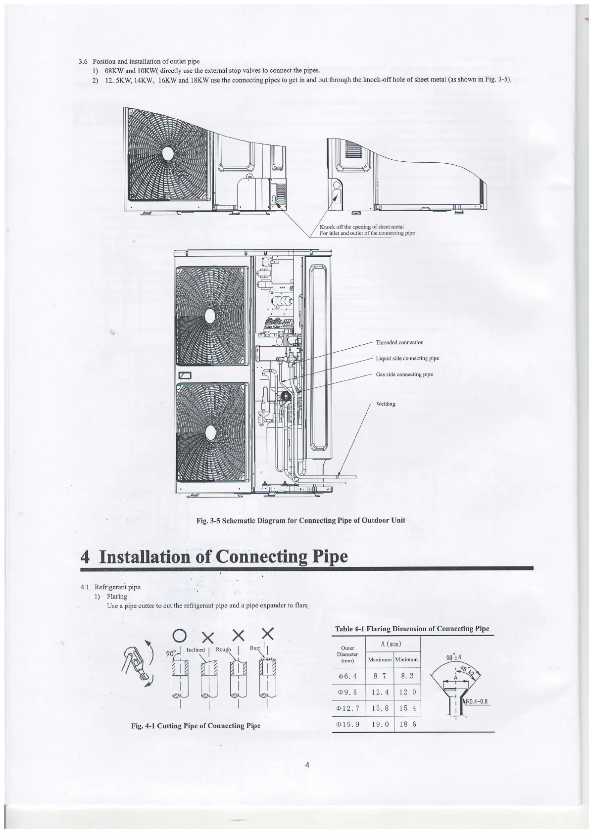
3.6 Position
md installation ofoutlet
pipe
1) 08KW and IOKW(
directly use the extemal
stop valves to comect
the
pipes.
2) 12.5KWl4KW, l6KWandlSKWusethecomectingpipestogetinmdoutthroughtheknock-offholeofsheetmetal(asshominFig.3-5).
Thcaded comection
Liquid side connecting
pipe
Gas side
comectirg
pipe
Welding
Fig.
3-5
Schematic Diagram
for Connecting
Pipe
of
Outdoor Unit
4 Installation of Connecting
Pipe
Knock olT the opening of shect
metal
For inlet
and outlet ofthe connecting
pipe
Table 4-1 Flaring
Dimension of Connecting
Pipe
Outer
Diameter
(lm)
A
(mm)
g0
t{
/-R\
\r-+*r.Y
r'lf-
Maxiruurn Minimw
,b6.4
8.7
8.3
(D9.5
12.4
12.0
at2.7
15. B
15. 4
o15.9
19.0
18. 6
4.i Refrigerant
pipe
,
1) Flaring
Use
a
pipe
cutter to cut the refrigerant
pipe
and a
pipe
expander to flare
X
"{t
W
a
I
OXX
90,
*n'\o
|
**t\
|
wtn M
A UJ H
ltl
N
Fig. 4-1 Cutting Pipe of Connecting
Pipe