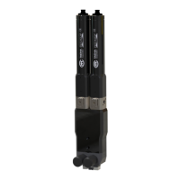
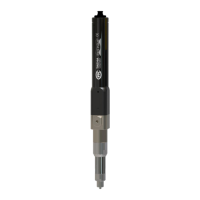
The TAEHA PRO DUO PUMP SYSTEM (PDP-1000) is a high-performance dispensing system designed for precise application of two-component materials. It utilizes a specialized eccentric screw structure, offering a simple yet highly efficient design. The system is complemented by a dedicated control panel with software, enabling a wide range of dispensing tasks with convenience, accuracy, and versatility.
Function Description:
The core of the system is the rotary auger pump, specifically engineered for long-term stability when handling two-component materials. This design significantly enhances pump efficiency and reproducibility compared to traditional positive displacement methods. Users can easily adjust the mix ratio and dispensing volume by controlling the number of turns and rotational speed of the rotor. The pump is capable of handling a broad spectrum of materials, accommodating varying viscosities and natural material changes. A key feature is the "sniff back" function, which prevents drop formation, ensuring clean dispensing. Maintenance is simplified and eco-friendly as it primarily involves replacing the mixer part, eliminating the need for detergents.
The system is available in two main configurations:
- PDP (Standard) System: In this setup, material suppliers (e.g., cartridges, tanks) are separated from the Pro-duo pump unit.
- PDPM (Module Type) System: This configuration integrates the material supplier (e.g., barrel, cartridge) directly with the Pro-duo pump unit, offering a more compact and integrated solution.
Important Technical Specifications (PDP-1000 Pro Duo Pump):
- Model: PDP-1000
- Dimensions (WxDxH): 67 x 35 x 340 mm
- Weight: 1.8 kg
- Input Pressure: 0 ~ 0.6 MPa
- Max Dosing Pressure: 2.0 MPa
- Viscosity Range: 10 ~ 300,000 cPs
- Dosing Volume/Rev: Approximately 2.2 ml
- Motor Speed: 0 ~ 120 rpm
- Accuracy of Dosing: ±2%
- Stator Material: FFKM / FKM / EPDM
- Material Inlet Port: Module Type: Inlet Adapter, Tap Type: BSPT 1/4"
- Material Outlet Port: Mix adapter A/B/C/F/K type
- Operating Condition: 10 ~ 40°C, 10 ~ 85%RH
Important Technical Specifications (PDC-100 Pro Duo Pump Controller):
- Model: PDC-100
- Weight: 3.6 kg
- Input Power: AC 100~240V 50/60Hz (1 phase), DC24V (max), ±10%
- Power Consumption: Max. 75W
- Display: 5" TFT LCD
- Operation Mode: Time / Steady / Purge / Ratio (4 Modes)
- Operation Memory: 15 channels (User Define)
- Operating Air Pressure: 0.5 MPa (Air Filter: 5μ)
- Air In Port: One touch fitting PC (Ø6, max. 0.7 MPa)
- Air Out Port: One touch fitting PC (Ø6, max. 0.7 MPa)
- Liquid Indicator Sensor: OK
- External Control: OK
- Interface: RS232, D-SUB 9 PIN
- Input Signal: Contact Input or NPN Open Collector Tr
- Dosing End Signal: NPN Open Collector Tr
- Operating Temperature: 10 ~ 40°C (Avoid direct sunlight)
- Operating Humidity: 10 ~ 85%RH (No condensation)
- Vibration Resistant: Less than 0.5G (G: acceleration of gravity)
Usage Features:
The system emphasizes ease of use, starting with the connection of the stator and rotor. A fixed tool is used to secure components while applying material to the stator and rotor, which are then rotated into position. A critical precaution is to never activate the pump without material in the stator, as this can cause damage.
Before liquid dispensing, air bubbles must be eliminated. After pump and controller settings are finalized, the D (Vent knob) should be rotated one to two rounds in the arrow direction to dispense bubbles and some liquid (approximately 5-10 seconds). Once bubbles are confirmed to be eliminated, the knob is closed. For this process, the motor speed should be set to a low (5-10 RPM) setting.
The setup process involves connecting motor cables to the pump, air piping from the PDC-100 to the material supply device (ensuring clean air supply of 5kgf/cm² or more and untwisted piping), and the foot switch (or external device) to the control terminal. After verifying the input power supply, the power switch is turned on. Material supply air pressure should be set according to material viscosity: 1-2kgf/cm² for less than 2000 cPs, and 2-5kgf/cm² for over 2000 cPs. The air vent knob on the pump is opened to remove air bubbles and ensure smooth material supply, then closed once liquid flows sufficiently. Finally, the system is switched to manual mode, discharge speed set to about 10%, and the discharge button pressed to check for bubble-free dispensing. Once confirmed, the appropriate mode and discharge amount are set for shot conditions, and dispensing is initiated via the shot button, external device, or foot switch.
Maintenance Features:
Regular inspections are crucial for the Pro Duo Pump System, encompassing both the Dispenser (Pro Pump) and Dispenser Controller.
- Material Supply: Always ensure sufficient material in the inlet port to prevent pump damage from overheating when idle.
- Operation Check: Immediately stop operation and inspect if any abnormal sound occurs during or at the start of operation.
- Periodic Inspections: Occasional (user-determined) and periodic (within a year) inspections are recommended to prevent malfunctions.
- Safety Precautions: Before any maintenance or inspection, it is imperative to take safety measures such as switching to manual mode, emergency stop, and powering off the equipment. Failure to power off can lead to electric shock or unintended equipment movement if sensors detect material or the inspector. Megger tests (insulation resistance measurement) should not be performed as they can cause malfunction.
- Part Replacement: Due to the functional use time, parts may age and cause equipment failure. Regular checks for trouble prevention and equipment preservation are necessary, with parts replaced upon abnormality.
Troubleshooting Guide:
The manual provides a comprehensive troubleshooting guide for common issues:
- If dispensing is not possible: Check air supply in the tank, controller power supply, presence of solution, solution loading in conduit line, air fitting connections, and for clogged nozzles or pump motor operation.
- If there is a change in dispensing volume: Check controller setting values, solution solidification in the chamber, needle clogging, air bubbles in conduit line/chamber, tank air supply pressure changes, and liquid connection fitting leaks.
- If there is a leak at the nozzle end during standby: Check for abrasion in the stator's rubber part, ensure tank air pressure is not set too high (it should only transport fluid to the pump chamber), and verify there's no continuous operation of the pump drive motor.
- If the pump drive motor does not operate: Check motor cable connection, controller set value, power supply status, and for solidified solution in the pump chamber.
- If solution leaks out of the pump: Check for damage to the o-ring between the chamber and seal block, and the abrasion status of the rotary seal in the seal block.
- If an abnormal noise occurs during pump operation: Check for damage to the bearing in the bearing block, abrasion status of the rotary seal in the seal block, and the condition of the motor reducer.
The system also features an alarm display on the front touch panel, indicating issues related to hardware protection, incorrect settings, or mishandling. In case of a hardware protection alarm, motor output is cut off, and the servo is turned off. Operation can only restart after the cause of the alarm is resolved and released. Some alarms may require a power cycle (reboot) after corrective action.