140 Disassembly and Reassembly TM8100/TM8200 Service Manual
© Tait Electronics Limited June 2006
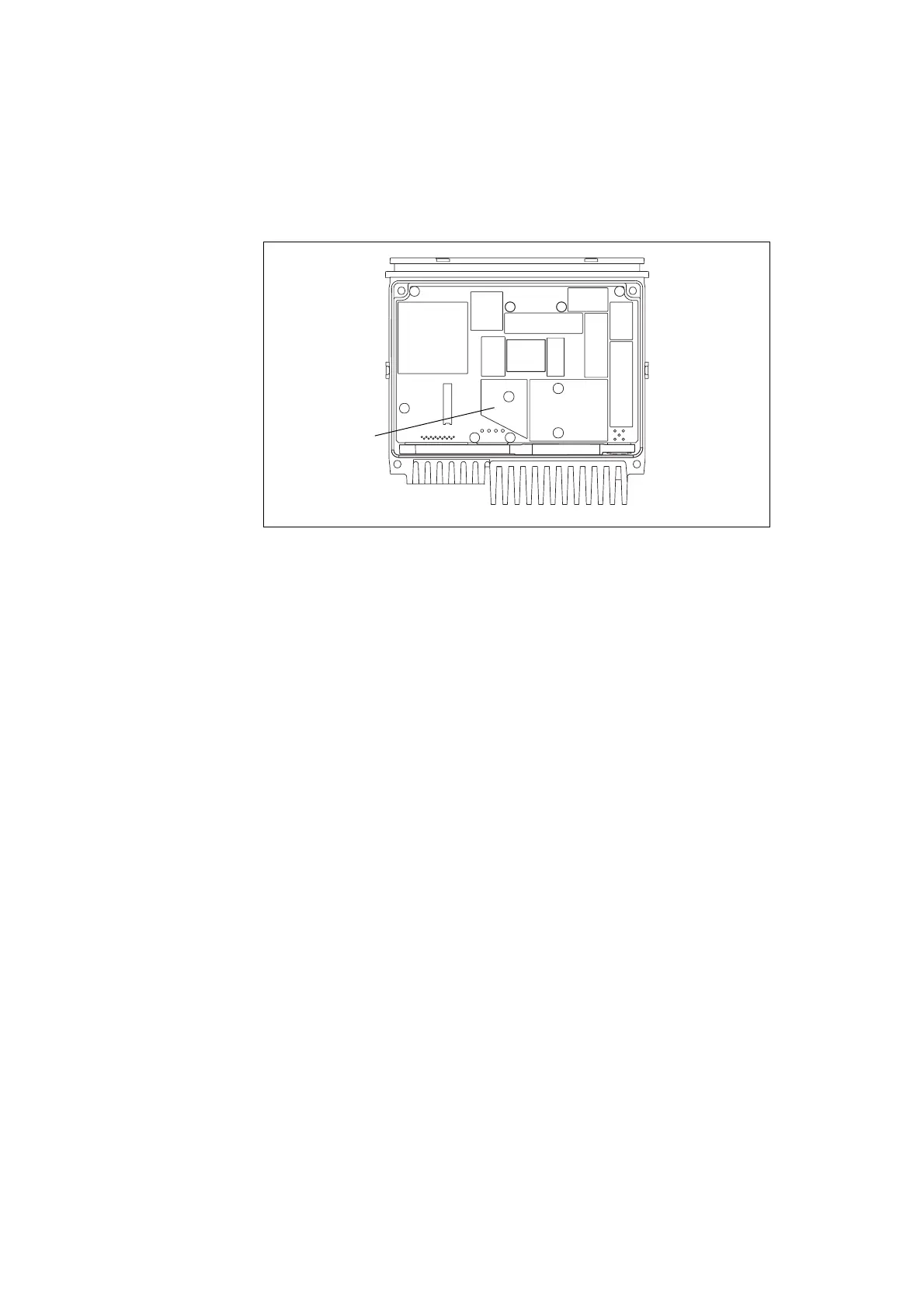
5. While pressing down firmly on the diagonal edge of the PAD TOP can
(refer to Figure 5.7), use a Torx T20 torque-driver to tighten the two
screws
I to 22lb·in (2.5N·m). This will ensure that the main board
is seated correctly on the bosses for the five internal screws
E.
6. Clean off any excess thermal paste on the heat-transfer block.
7. Screw in the five screws
E through the main board by hand as far as
possible. Use a Torx T10 torque-driver to tighten the screws to
17lbf
·in (1.9N·m).
8. Fit the RF connector seal
j. Ensure that the seal is properly seated
around its entire periphery.
9. If an auxiliary connector bung
h was fitted, fit the bung.
Closing the
Radio Body
The circled number in this section refer to the items in Figure 5.3 on
page 133.
1. If an internal options board is fitted inside the lid, connect the loom
to the internal options connector.
2. Inspect the main seal in the lid for damage, and replace if necessary.
3. Place the lid assembly
D on the chassis G.
4. Use a Torx T20 torque-driver to tighten the four screws
c to 22lbf·in
(2.5N
·m).
5. Slide the cover
b over the radio body and snap holes in the side of
the cover over the screw bosses.
6. Inspect the control-head seal for damage, and replace if necessary.
Figure 5.7 PAD TOP can on the top side of the main board
PAD TOP can