146 Disassembly and Reassembly TM8100/TM8200 Service Manual
© Tait Electronics Limited June 2006
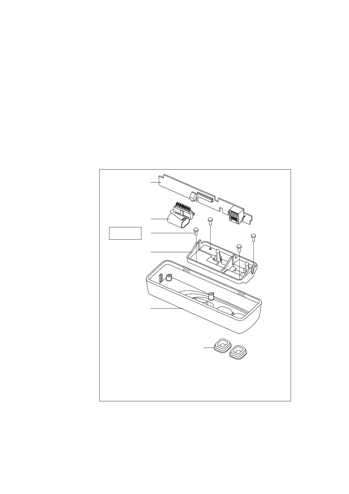
5.4.3 RJ45 Control Head
Disassemble only as much as necessary to replace the defective parts.
Reassembly is carried out in reverse order of the disassembly.
The circled numbers in this section refer to the items in Figure 5.12.
1. Release the clip of the PCB bracket
E and remove the control-head
board
B.
2. Disconnect the control-head loom
C from the control-head-board
B.
3. Use a Torx T10 screwdriver to unscrew the four screws
D and
remove the PCB bracket
E.
Figure 5.12 Components of the RJ45 control head
B
control-head board
E
PCB bracket
C
control-head loom with female-female adapter
F
front panel
D
3 x 8 PT screw (x4)
G
RJ45 bung (x2)
B
D
E
F
G
x4
C
Torx T10
5lb·in (0.6N·m)
x2
 Loading...


