TM8100/TM8200 Service Manual Disassembly and Reassembly 147
© Tait Electronics Limited June 2006
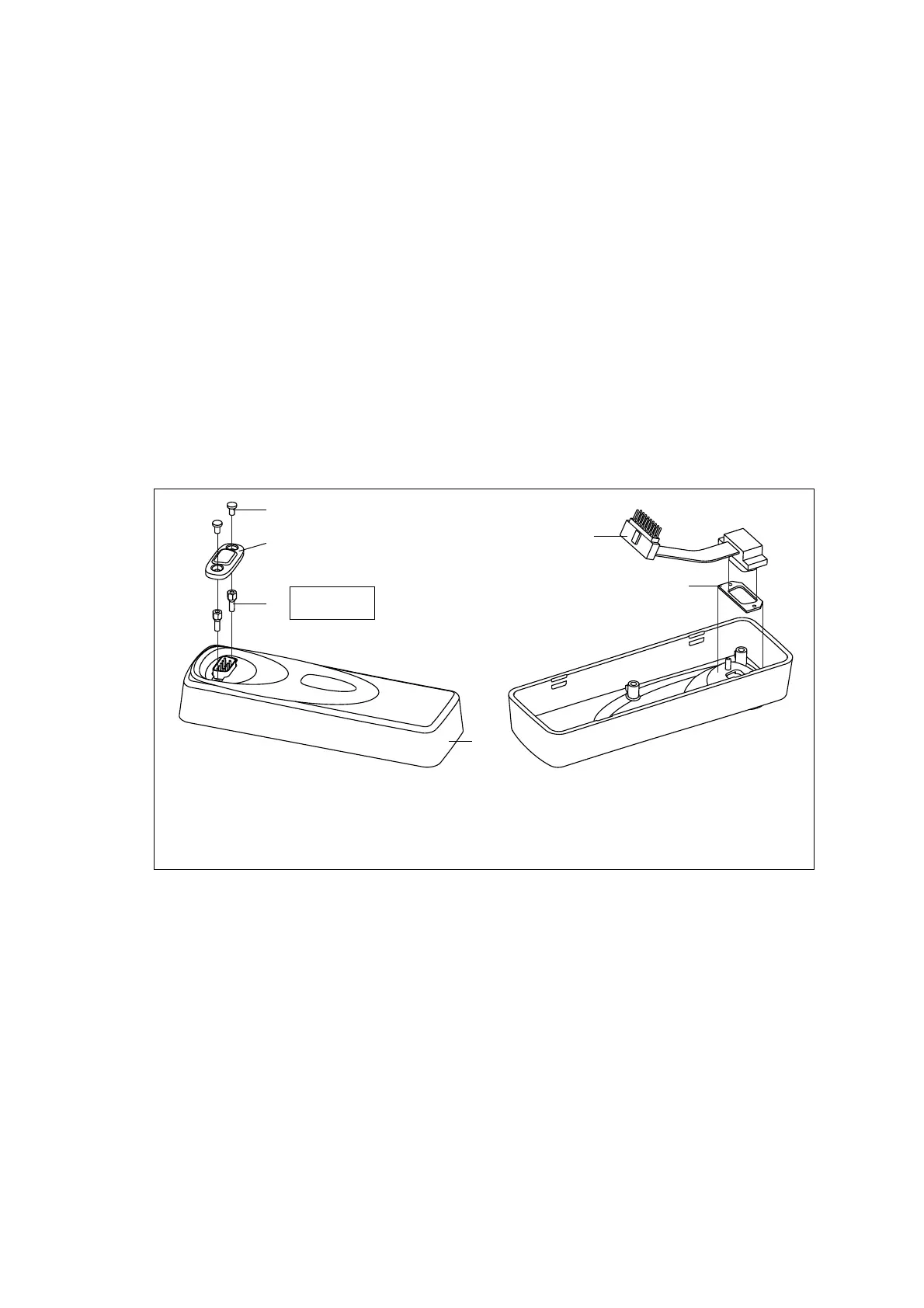
5.4.4 Blank Control Head
Disassemble only as much as necessary to replace the defective parts.
Reassembly is carried out in reverse order of the disassembly.
The circled numbers in this section refer to the items in Figure 5.13.
1. Note whether the cover seal
C is fitted or not. If it is fitted, remove
the two screws
B and remove the cover seal. Note that the radio must
be returned to the customer in its original configuration.
2. Note whether an options board (not shown) is fitted inside the
control head. If a an options board is fitted, remove the screws and
remove the options board.
3. Remove the lock-nuts
D and remove the foam seal F and the control
head loom
G.
Figure 5.13 Components of the blank control head
B
UNX 4-40 x 3/16-inch pan Pozi screw (x2)
E
front panel
C
cover seal
F
foam seal
D
lock-nut (pair)
G
control-head loom with female-female adapter
F
3829z_01
x2
B
E
x2
D
C
G
3/16 inch (5mm)
4lb·in (0.45N·m)