168 Power Supply Fault Finding TM8100/TM8200 Service Manual
© Tait Electronics Limited June 2006
Task 3 —
Check Linear
Regulators
This task describes the general procedure for checking any linear regulator.
There are two possible faults: either the regulator has failed and prevents the
radio from powering up, or the regulator voltage is incorrect. (The regulator
IC might or might not have been removed during earlier checks.)
1. Disconnect the 13.8 V supply. Check for continuity and shorts to
ground (if not already done) on the input, output and control line of
the relevant regulator IC. Repair any fault.
2. If the regulator IC has been removed, resolder it in position.
3. Reconnect the 13.8 V supply and press the
ON/OFF key. If the radio
powers up or the correct regulator voltage is restored, return to
“Initial Tasks” on page 149. If the repair failed, go to Step 4.
4. Disconnect the 13.8 V supply. Replace the regulator IC with a spare.
Reconnect the 13.8 V supply and press the
ON/OFF key. If the radio
powers up or the correct regulator voltage is restored, go to “Final
Tasks” on page 157. If the repair failed, replace the board and go to
“Final Tasks” on page 157.
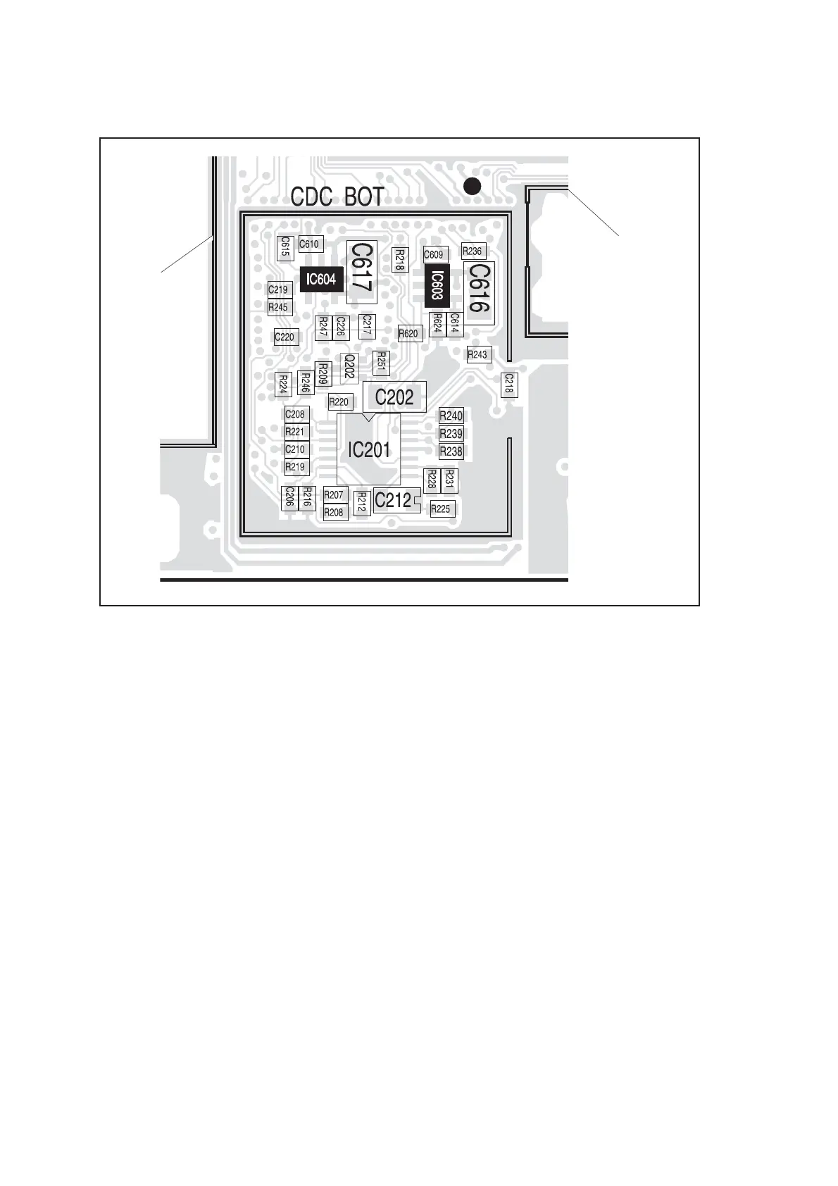
Figure 7.3 Power-supply circuitry under the CDC BOT can, including 3V regulator IC603 and 2.5V
regulator IC604
LO2 BOT CAN
CAN FOR
DIGITAL
BOARD
TP601
 Loading...


