144 Disassembly and Reassembly TM8100/TM8200 Service Manual
© Tait Electronics Limited June 2006
5.4.2 Control Head with 1-, 2- or 3-Digit Display
Disassemble only as much as necessary to replace the defective parts.
Reassembly is carried out in reverse order of the disassembly.
The circled numbers in this section refer to the items in Figure 5.11 on
page 145.
1. With your fingers, pull off the volume control knob
I.
Do not use any tools as this might cause damage.
2. If an optional circuit board
C for a concealed microphone is fitted,
unplug it from the control-head board
E (refer to Figure 5.10).
3. If a concealed microphone
1) is fitted, unsolder the microphone leads
from the control-head board. The leads are soldered to pads on the
board as shown in Figure 5.10.
4. Note whether the speaker
J is connected or disconnected. If it is
connected, disconnect the speaker cable from the speaker connector
of the control-head board (refer to Figure 5.10). Note that the radio
must be returned to the customer in its original configuration.
5. Use a Torx T10 screwdriver to unscrew the three screws
D securing
the control-head board. The screws are labelled screw 1 to screw 3;
these numbers are also inscribed on the PCB. The control-head board
is now held down only by the clips labelled clip 1 to clip 3 in
Figure 5.10.
6. While pressing on the shaft of the volume-control potentiometer,
push clip 2, clip 1 and then clip 3 away from the control-head board.
The board will be freed from the space-frame. Remove the board.
7. While pulling upwards on the space-frame
G at the corner where the
microphone connector is situated, release the clips labelled
B to G in
Figure 5.11 in the order:
B and C, D and E, and then F and G.
To release each clip use a 3/16 inch (5mm) flat-bladed screwdriver to
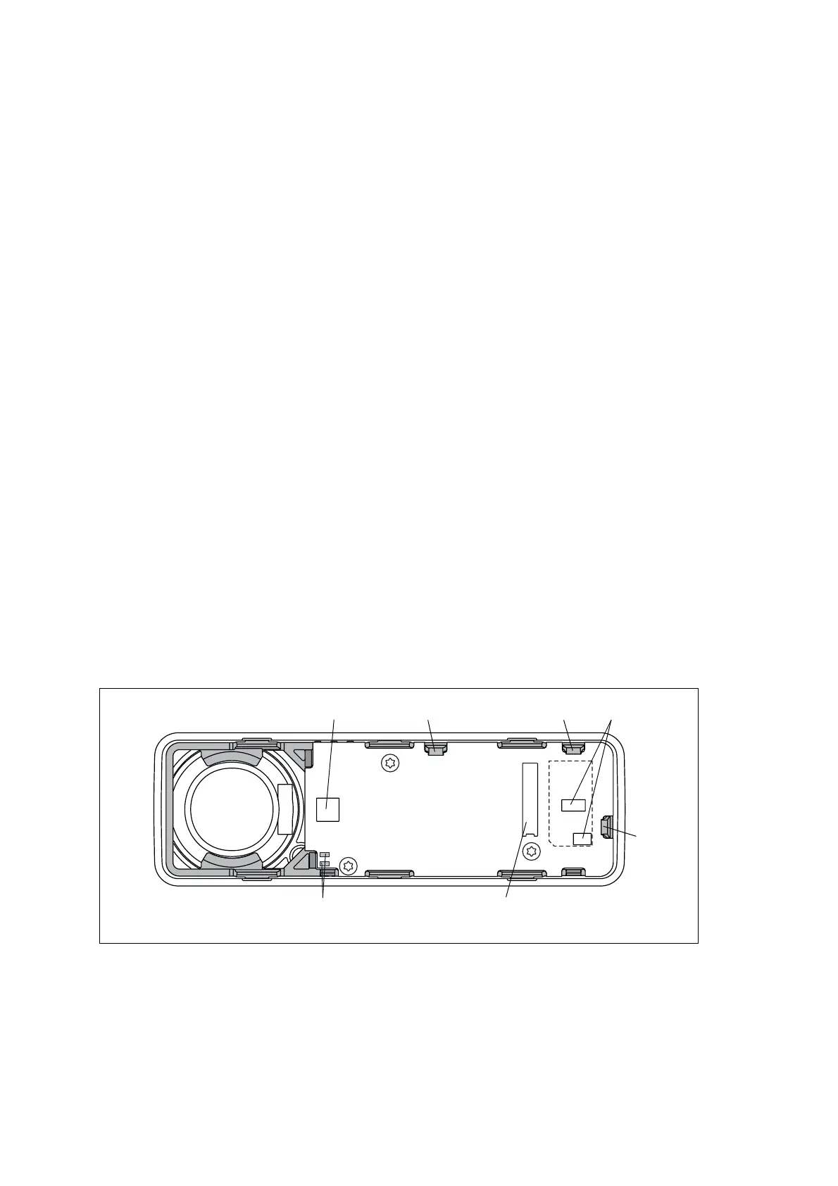
Figure 5.10 Connectors and clips of the control-head board (1-, 2- or 3-digit display)
connector for speaker
connectors for
optional circuit board
3830z_01
pads for leads of
concealed microphone
clip 1 clip 2
clip 3
connector for
control-head loom

 Loading...


