TM8100/TM8200 Service Manual Disassembly and Reassembly 145
© Tait Electronics Limited June 2006
lever the clip out of its recess. Pulling on the space-frame helps release
the clips.
Important When fitting the space-frame
G, make sure that the clips
labelled
B to G fully snap into the front panel assembly.
If necessary, use a flat-bladed screwdriver to push down the
clips until they snap into place.
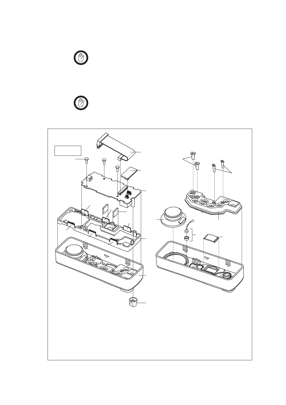
8. Remove the elastomeric strips
F, speaker J, LCD 1!, keypad 1@,
lightpipes
1$ and 1%, and, if fitted, the concealed microphone 1).
Important When replacing the LCD, carefully remove the protective
plastic film from the LCD. Take care not to scratch the soft
polarizer material on the top side of the LCD.
Figure 5.11 Components of the control head (1-, 2- or 3-digit display)
B
control-head loom with female-female adaptor
I
knob for volume-control potentiometer
C
control-head options board (optional)
J
speaker
D
3 x 8 PT screw (x3)
1)
concealed microphone (optional)
E
control-head board
1!
LCD
F
elastomeric strip (x2)
1@
keypad
G
space-frame
1#
short light pipe
H
front panel assembly
1$
long light pipe
J
B
1^
G
I
H
1)
1&
1#
1%
1$
F
E
1!
3828z_01
D
x3
B
C
E
F
x2
G
H
1)
J
1@
1#
1$
1!
I
B
D
F
G
E
C
Torx T10
5lb·in (0.6N·m)

 Loading...


