TOWER PARTS Kit Installation Instructions
Page 3 of 4 Rev. 1/26/2017
Copyright 2017 Talkaphone • 7530 North Natchez Avenue • Niles, Illinois 60714 • Phone 773.539.1100 • info@talkaphone.com • www.talkaphone.com.
All prices and specifications are subject to change without notice. Talk-A-Phone, Scream Alert, WEBS and WEBS Contact are registered trademarks of Talkaphone All rights reserved.
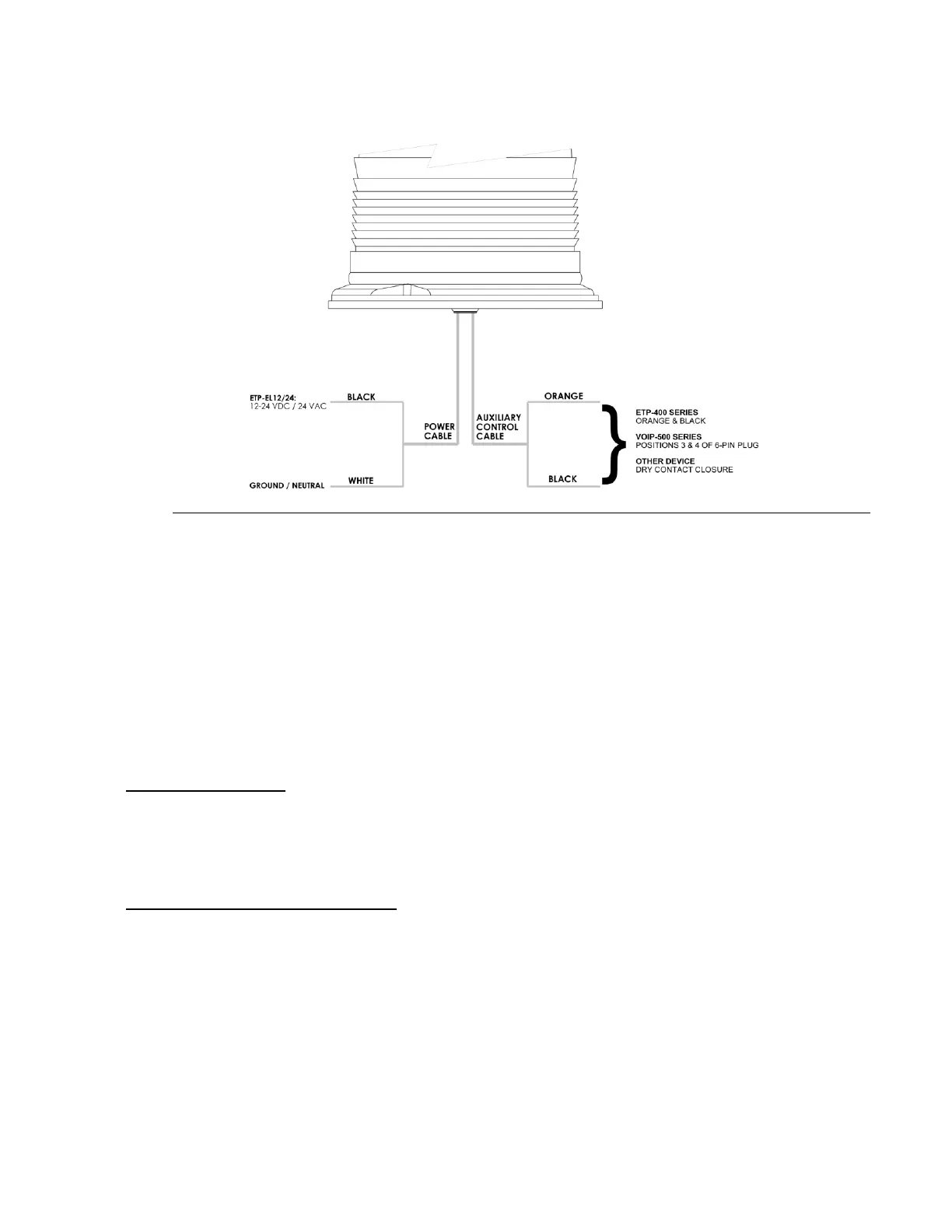
Figure 3: Electrical connections to the ETP-EL12/24 LED Blue Light
6. When using the ETP-EL Series LED Blue Light with ETP-400 Series Emergency Phones, connect the
orange and black auxiliary control cable pair of the LED Blue Light to the orange and black wires of the
emergency phone. Refer to the emergency phone manual for information regarding the programming
of your phone.
7. When using the ETP-EL Series LED Blue Light with VOIP-500 Series Emergency Phones, connect the
orange and black auxiliary control cable pair of the LED Blue Light to positions 3 and 4 (Aux. Output 2)
of the 6-pin connector plug of the VOIP-500 Series Phone.
8. Re-attach the access panel over the access opening.
IV. Power Requirements:
ETP-EL: 96-132VAC, 7.8 Watts (35A peak inrush)
ETP-EL12/24: 10-30VDC / 20-28VAC, 7.5 Watts, 1.5 Watts low power steady mode (18A peak inrush)
LED Panel Light: 12VDC, 1.2 Watts and 24VDC / 24 VAC / 120VAC, 1.63 Watts
V. OP4 / OP5 Arm Installation (optional)
1. Remove tower cap plate. – See Figure 4 –
2. Pull the LED Blue Light and camera cables through hollow arm channel.
3. Attach LED Blue Light using the three (3) 10-24 tamperproof screws provided in the OP 4 TOWER
PTS package. If installing a camera, attach the camera to the 1.5” NPT coupling of the arm. (Hardware
is not provided for the camera). Pull cables into tower.
4. Nuts and bolts are provided in the OP 4 TOWER PTS to attach the arm to the tower itself. Reach
through the top of the tower to tighten the bolts. Replace the tower cap plate.
 Loading...