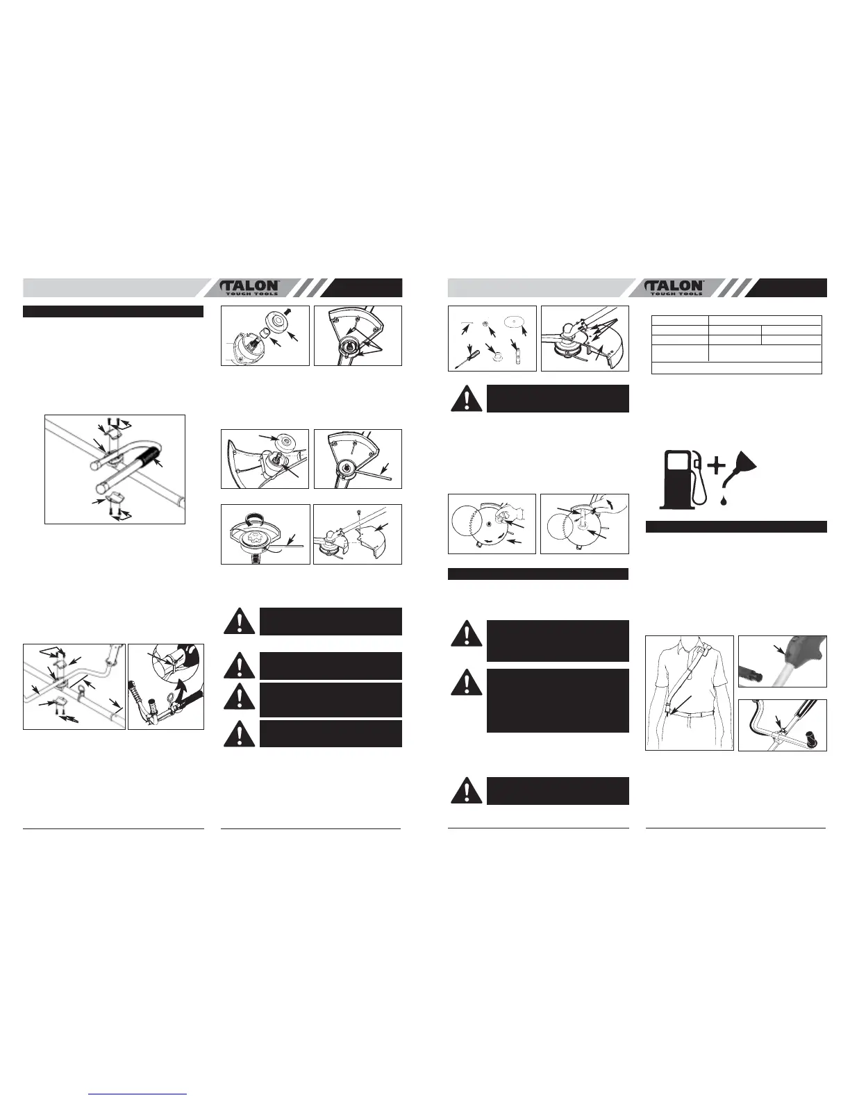
4. Install blade (D) with teeth pointing CLOCKWISE as
shown in the illustration (Fig. 4C).
5. Install flange (F) with FLAT SURFACE facing blade
(Fig. 4C).
NOTE: Make sure blade is centered on collar arbor.
6. Tighten nut (C) securely by turning it COUNTER-
CLOCKWISE with socket wrench (G). Remove hold-
ing pin (Fig. 4D).
• FUEL
Use regular grade unleaded gasoline mixed with 2-cycle
engine oil in 25:1 ratio for best results. Use mixing ratios
in Section FUEL MIXING TABLE.
• MIXING FUEL
Mix fuel with Talon brand 2 cycle oil in an approved con-
tainer. Use mixing table for correct ratio of fuel to oil.
Shake container to ensure thorough mix.
• FUEL MIXING TABLE
• RECOMMENDED FUELS
Some conventional gasolines are being blended with oxy-
genates such as alcohol or an ether compound to meet
clean air standards. Your Talon engine is designed to
operate satisfactorily on any gasoline intended for auto-
motive use including oxygenated gasolines.
• FUEL AND LUBRICATION
• SHOULDER STRAP
1. Put the strap on so it is over your LEFT shoulder.
2. Attach the clip (A) to the ring (B) on the trigger grip
(AT3323/AT3323S) (Fig. 5A and 5B). Attach clip (A)
to shaft ring for model AT3324 & AT3324S.
3. Adjust length of shoulder strap so linehead is parallel
to the ground as it hangs from the strap. A few prac-
tice swings without starting engine should be made to
determine correct balance.
NOTE: Detach the shoulder harness from the unit before
starting engine.
4
GB GB
5
• “J” HANDLE ASSEMBLY
(AT3323/
AT3323S)
1. To install handle onto unit, you will need the following
components from your user kit: “J” handle (A), fixing
holder (B), clamps (C) and screws (D). (Fig. 1A)
2. Install the fixing holder (B) on the shaft around 4” (10-
12cm) away from the end of the grip, put the clamp
(C)over shaft and tighten the 2 screws (D).
3. Install the J handle (A) on the fixing holder, put the
other clamp (C) over J-handle and tighten the other 2
screws (D).
• “Bike¨ HANDLE INSTALLATION (AT3324/
AT3324S)
1. To install handle onto unit, you will need the following
components from your user kit: “U” handle (A), fixing
holder (B), clamp (C) and screws (D). (Fig. 1B)
2. Install the fixing holder (B) on the shaft around 4” (10-
12cm) away from the end of the grip, put the clamp
(C) and tighten the 2 screws (D).
3. Install the U handle (A) on the fixing holder, put the
other clamp (C) and tighten the other 2 screws (D).
4. Install wire tie (E) included in the user kit as shown
(Fig. 1C).
• BLADE GUARD INSTALLATION
1. Remove gear collar (A) from the threaded gear hous-
ing shaft (Fig. 2A).
2. Place the shield on the gear housing and align the
mounting holes. Insert screws (B) as shown in illus-
tration and tighten securely (Fig. 2B).
3. Reinstall the gear collar (A). Ensure the collar spacer
(C) is in place or the collar will rub the gear housing
(Fig. 2A).
• LINEHEAD INSTALLATION
1. Install gear collar (A) ensuring that collar spacer (B) is
in place (Fig. 3A).
2. Insert holding pin (C) and thread linehead onto shaft.
Tighten linehead by hand only (Fig. 3B and 3C).
• DEBRIS SHIELD SKIRT INSTALLATION
Turn the unit over and install the debris shield skirt (A) as
shown (Fig. 3D).
• BLADE INSTALLATION
1. To install the blade you will need the items illustrated
below (screwdriver not provided): holding pin (B),
retaining nut (C), blade (D), screwdriver (E), flange
(F), socket wrench (G) (Fig. 4A)
2. Remove three screws (H). Remove the skirt (A). Use
the holding pin to prevent the collar from turning while
removing the linehead (turn CLOCKWISE) (Fig. 4B).
3. Leave the holding pin (B) in place.
ASSEMBLY INSTRUCTIONS
Fig. 1A
A
B
C
D
D
C
Fig. 1B
D
E
D
B
A
C
C
4” (10-12cm)
Fig. 1C
Fig. 2BFig. 2A
A
B
C
Fig. 3A Fig. 3B
C
A
B
Fig. 3D
A
Fig. 3C
C
CAUTION: Skirt must be installed to proper-
ly dispense cutter line and protect operator
CAUTION: NEVER use unit if blade is
warped or has teeth that are chipped or miss-
ing. Replace a damaged blade immediately.
CAUTION: NEVER operate unit with a blade
unless metal blade guard is properly
installed. NEVER operate a unit with a dam-
aged guard.
CAUTION: Always wear heavy-duty work
gloves when handling and installing a blade.
OPERATING INSTRUCTIONS
Fig. 4B
Fig. 4A
A
E
B
C
F
D
G
H
WARNING: Be sure the blade center hole is
properly sized to the collar arbor.
Fig. 4DFig. 4C
F
C
D
G
FUEL AND LUBRICATION
WARNING: Never use straight gasoline in your
unit. This will cause permanent engine damage
and void the manufacturer’s warranty for that
product. Never use a fuel mixture that has been
stored for over 90 days.
WARNING: If 2-cycle lubricant other than Talon
Custom Lubricant is to be used, it must be a pre-
mium grade oil for 2-cycle air cooled engines
mixed at a 25:1 ratio. Do not use any 2-cycle oil
product with a recommended mixing ratio of
100:1. If insufficient lubrication is the cause of
engine damage, it voids the manufacturer’s
engine warranty for that occurrence.
WARNING:
Lack of lubrication voids engine
warranty. Gasoline and oil must be mixed at
25:1.
GASOLINE 25:1 Ratio Lubricant
5 Liters 6.7 oz. 200ml (cc)
1 lmp. Gal. 6.1 oz. 180ml (cc)
Mixing 25 Parts Gasoline
Procedure to 1 part Lubricant
1ml = 1cc
Gasoline and
Oil Mix 25:1
Fig. 5A
A
Fig. 5B
B
Fig. 5C
B
 Loading...