4
GB
GENERAL INFORMATION
1
2
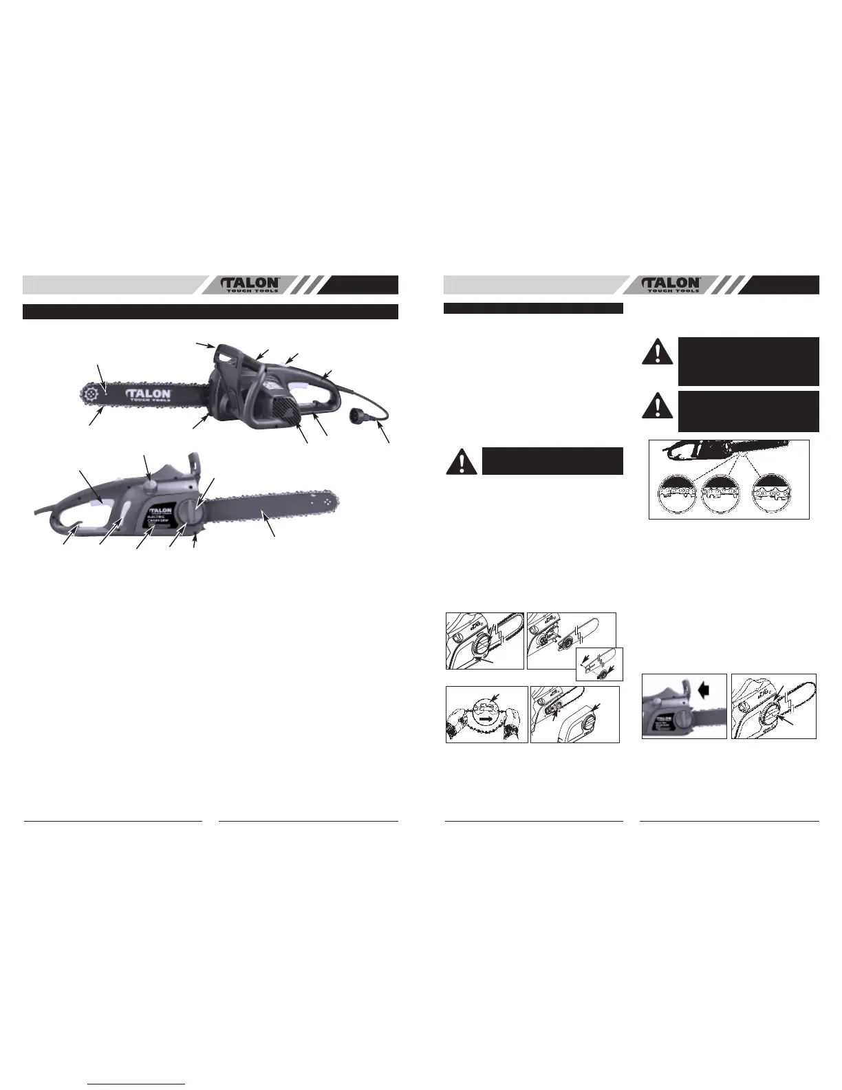
1. Rear Handle
2. Oil Tank Cap
3. Trigger Start
4. Sprocket cover
5. Chain Cover Control Knob
6. Chain Tension Ring
7. Electric Motor
8. Electric Cord
9. Chain Brake Lever / Hand
Guard
10. Lock / Button
11. Front Handle
12. Guide Bar
13. Saw Chain
14. Spiked Bumper
15. Rear hand Guard
16. Guide Bar Nose
17. Oil Tank Inspection Window
18. Cord Retainer
19. Chain Catcher
3
7
4
13
6
8
9
10
11
12
14
15
16
17
18
• SAFETY FEATURES
Numbers preceding the descriptions correspond with the numbers above to help you locate the safety feature.
3 TRIGGER START / STOP SWITCH stops saw motor when released.
9 CHAIN BRAKE LEVER / HAND GUARD activates the chain brake and protects the operator’s left hand in the
event it slips off the front handle while saw is running.
7 ELECTRIC MOTOR is double insulated for added safety.
10 LOCK / OFF BUTTON prevents accidental acceleration of the saw motor. The trigger cannot be squeezed unless
lock/off button is pushed forward to end.
13 LOW-KICKBACK CHAIN helps significantly reduce kickback, or the intensity of kickback, due to specially
designed depth gauges and Guard links.
19 CHAIN CATCHER reduces the danger of injury in the event saw chain breaks or derails during operation. The
catcher is designed to intercept a whipping chain.
5
19
5
GB
•
INTRODUCTION
This unit is designed for occasional homeowner use and
should not be used for commercial purposes or subjected
to heavy continuous use.
Your new chain saw can be used for a variety of projects
such as cutting firewood, making fence posts, felling small
trees, limbing, pruning at ground level, and light carpentry.
Cut only wood or wood products with your saw.
• ASSEMBLY REQUIREMENTS
Your new chain saw will require adjustment of chain and
filling the oil tank with lubricating oil before the unit is
ready for operation. Do not start the saw motor until the
unit is properly prepared. Read all instructions carefully.
Do not install any other size bar and chain than what is
recommended for your model.
• GUIDE BAR / SAW CHAIN INSTALLATION
TO INSTALL GUIDE BAR & SAW CHAIN:
1. Place power unit on flat surface.
2. To remove the side cover (A), turn the knob (B) count-
er-clockwise. (Fig. 3A)
3. Screw (C) the tension plate (D) on the bar. (Fig. 3B)
4. Spread the chain out with the cutting edges (E) of the
chain pointing in the DIRECTION OF ROTATION (Fig.
3C).
5. To fit the chain on the bar, turn the tension plate (D)
counter-clockwise to the end. Install the chain and bar
on the power unit, turn the tension plate (D) clockwise
and then put the side cover (A) on. (Fig. 3D)
6. Turn the knob clockwise, adjust the chain tension pin
and then fasten the knob.
7. After running the chain saw around 1 hour, adjust the
chain tension to 2mm.
• SAW CHAIN TENSION ADJUSTMENT
Proper tension of the saw chain is extremely important
and must be checked before starting, as well as during,
any cutting operation. Taking the time to make needed
adjustments to the saw chain will result in improved cut-
ting performance and prolonged chain life.
NOTE: A new chain and bar will need readjustment after
as few as 5 cuts. This is normal during the break-in peri
-
od, and the interval between future adjustments will
lengthen quickly (Fig. 4).
TO ADJUST SAW CHAIN TENSION:
NOTE: Make sure the chain brake is disengaged.
Disengage the chain brake (A) by pulling it backward (Fig.
5A).
1. To adjust the chain tension release locking knob (B)
by turning counter clockwise. (Fig. 5B)
2. To tighten chain tension turn adjustment ring (A)
clockwise. (Fig. 5B)
3. Lock bar in place by tightening locking knob (B).
NOTE: If the chain is difficult to rotate or if it binds on the
guide bar, too much tension has been applied and must
be adjusted as follows:
4. Release locking knob (B).
5. Release chain tension by turning adjustment ring (A)
counter clockwise.
6. Tighten locking knob.
ASSEMBLY INSTRUCTIONS
CAUTION: Disconnect the chain saw from
mains before checking adjusting the chain
saw tension.
Fig. 3A
B
A
Fig. 3B
C
D
Fig. 3C
D
Fig. 3D
A
E
CAUTION: If a chain is TOO LOOSE or TOO
TIGHT, the bar chain and saw bearings will
wear more rapidly. Study Fig. 4 for informa-
tion concerning correct cold tension (A), cor
-
rect warm tension (B), and as a guide for
when saw chain needs adjustment (C).
CAUTION: If the chain is too loose, more
than 3mm after applying down force with fin-
ger, as shown in Fig. 4. It needs to be adjust-
ed, otherwise the stopping time might be
over the limit.
Fig.4
A
B
C
B
A
A


 To Next Page