8
1.2 Output Voltage Control
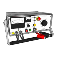
The output from the equipment is controlled from zero by means of the output control. To
increase the output voltage turn the control knob in a clockwise direction.
Note: The output cannot be energised unless the regulator knob is set to zero, thus operating the
zero voltage interlock switch.
1.3 Overload Protection
The equipment is fitted with a fuse and variable overload protection circuits as standard.
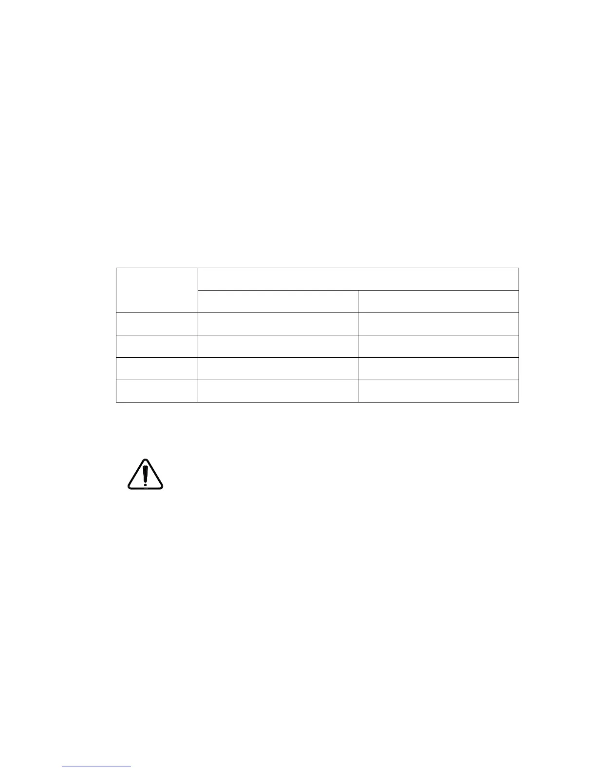
1.3.1 Variable overload
The variable overload protection system senses current changes in the high voltage circuit.
The trip levels are adjustable in two ranges each of 6 steps giving 2-12% and 20-120% rated
current.
20, 40, 60, 80, 100, 120mA
50, 100, 150, 200, 250, 300mA
60, 120, 180, 240, 300, 360mA
40, 80, 120, 160, 200, 240mA
The range change and selector switches are located on the front panel of the instrument. The
circuit will activate when the load current exceeds that set by the trip level selector switch.
The variable overload trip circuit does not limit the output current.
 Loading...