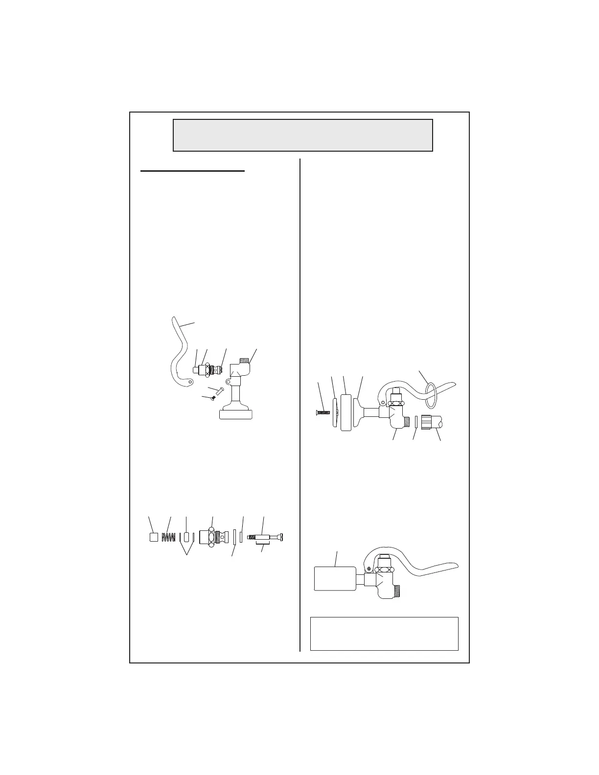
To replace worn parts:
1. Shut off water supply and drain
lines. For ease of disassembly and
reassembly, the handle grip can be
removed from no.3.
2. Unscrew no.5 and no.6 to remove
no.4. Unscrew and remove no.16
from no.3.
3. Hold no.20 with pliers in one
hand, and with screwdriver, carefully
unscrew no.13 from no.16.
4. Apply no.21 over smooth portion
of no.13. Replace no.14, no.15, no.17,
no.18 & no.19 with new parts. Dab
no.21 onto valve side of no.19 before
replacing.
3
6. Reinsert no.16 in no.3 and tighten
securely.
7. Reassemble no.4, no.5 and no.6
on no.3.
8. For B-0107 ONLY: To replace
no.9, unscrew no.11 and disassemble.
Make sure the groove side of no.9
fi ts over no.8, and no.10 rest on ridge
side. See Figure A.
9. To replace no.2, unscrew handle
grip from no.3 and replace with new
no.2.
10. Reassemble; turn on water check
for leaks.
General Instructions
4
16
20
5
6
4
16 14 13181920
17 15
5. Reassemble no.16 by inserting
no.13 through all parts. Hold no.20
with pliers, and carefully screw no.13
into no.20 until screw feels tight. Do
not use excessive force.
0.65 GPM
60 PSI
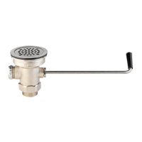
11. For B-0107-C ONLY: To replace
no.23, slide no.23 off no.25, and slide
a new no.23 back onto no.25. See
Figure B.
Caution: Turn off water supply at
base faucet when not in use.
Figure A
Figure B
11
10 9 8
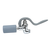
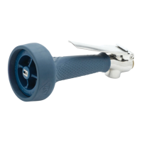
1
3 2 Handle
Grip
23
13
apply no.21
here