Appendix
C
I
MS-DOS Memory Map
ROM
BIOS
Data
Area
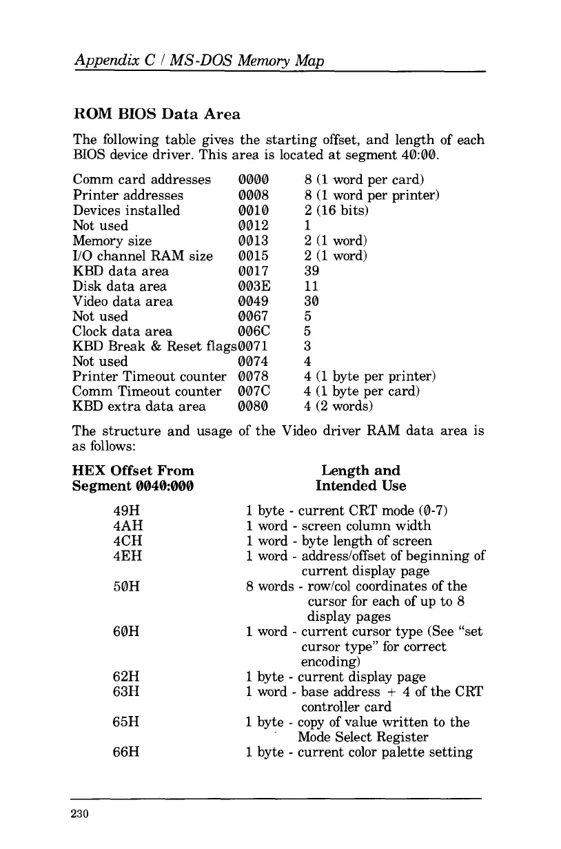
The following table gives the starting offset, and length of each
BIOS device driver. This area
is
located at segment 40:00.
Comm card addresses 0000
8
(1
word per card)
Printer addresses 0008
8
(1
word per printer)
Devices installed 0010 2 (16 bits)
Not used 0012
1
Memory size 0013 2
(1
word)
I/O channel RAM size 0015 2
(1
word)
KBD data area 0017 39
Disk data area 0033
11
Video data area 0049 30
Not used 0067
5
Clock data area 006C
5
KBD Break
&
Reset flags0071
3
Not used 0074
4
Printer Timeout counter 0078 4
(1
byte per printer)
Comm Timeout counter 007C 4
(1
byte per card)
KBD extra data area 0080
4
(2 words)
The structure and usage of the Video driver RAM data area is
as
follows:
HEX
Offset From Length and
Segment
0040:000
Intended
Use
49H
4AH
4CH
4EH
50H
1
byte
-
current CRT mode (0-7)
1
word
-
screen column width
1
word
-
byte length of screen
1
word
-
addressloffset of beginning of
current display page
8
words
-
row/col coordinates
of
the
cursor for each of up
to
8
display pages
60H
1
word
-
current cursor type (See “set
cursor type”
for
correct
encoding)
62H
63H
65H
66H
1
byte
-
current display page
1
word
-
base address
+
4 of the CRT
1
byte
-
copy of value written
to
the
1
byte
-
current color palette setting
controller card
’
Mode Select Register
230
 Loading...


