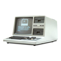
Do you have a question about the Tandy TRS-80 Model II and is the answer not in the manual?
Step-by-step guide for diagnosing and resolving system issues.
Summary of diagnostic checks performed upon computer power-up.
Specific instructions for troubleshooting various error messages and symptoms.
Detailed instructions for replacing various hardware components.
Description of the bus steering logic controlling data flow.
Details on the logic for manual and power-on system resets.
Explanation of how the system clock signals are generated.
Description of the interrupt handling and priority logic.
Explanation of the controller's decoding logic for data and commands.
Description of the logic governing the bus interface.
Details on the interface logic between the Z80 PIO and the controller.
Information on the FD1791 integrated circuit used in the controller.
Description of the interface between the processor and the controller.
Details on the specific interface connections for the FD1791.
Description of the process for reading data from a disk.
Description of the process for writing data to a disk.
Explanation of the logic connecting the FDC and Floppy Disk Drive.
Explanation of the logic used to recover clock signals during read operations.
Detailed explanation of the high-speed timing signals.
Details on the Cathode Ray Tube Controller and its functions.
Logic for selecting between RAM and Video RAM.
Detailed technical specifications for the video monitor.
Description of the video amplifier stage within the monitor.
Explanation of the horizontal drive signal generation and path.
Procedures for installing the video monitor.
General safety precautions for servicing the video monitor.
Explanation of the memory board's operational principles and data flow.
Description of the data bus buffers on the memory board.
Explanation of address buffers and memory select logic.
Procedures for verifying the functionality of the memory boards.
Explanation of the floppy disk drive's operational principles.
Instructions for configuring jumpers on the disk drives.
Switch configurations for the CDC disk drives.
General troubleshooting procedures for the disk system.
Troubleshooting steps for AC or DC power-related issues.
Troubleshooting steps for general operational failures.
Specific troubleshooting for read or write errors.
Procedures for replacing components within the disk system.
Steps for disassembling the disk system.
Technical specifications for the AA11080 power supply unit.
Procedures for troubleshooting the AA11080 power supply.
Required equipment and setup for testing the power supply.
Procedure for safely starting up the power supply.
Troubleshooting steps for when the power supply has no output.
Procedure for checking the power supply fuse.
Checking primary components of the power supply.
Checking major secondary components of the power supply.
Procedure for checking the B+ voltage level.
Checking the waveforms of transistor Q1.
Procedures for testing the performance of the power supply.
| Manufacturer | Tandy Corporation |
|---|---|
| Model | TRS-80 Model II |
| Category | Desktop |
| Release Year | 1979 |
| CPU | Zilog Z80 |
| CPU Speed | 4 MHz |
| RAM | 32 KB (expandable to 64 KB) |
| ROM | 12 KB |
| Operating System | TRS-DOS |
| Ports | Parallel port, serial port |
| Keyboard | Full-sized keyboard with numeric keypad |