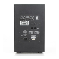
C): Power Switch
The power switch is of a rocker style with international
markings on it indicating when the amplifier is ON or OFF.
When the switch is placed in the (-) position the amplifier
is ON. When the switch is placed in the (O) position the
amplifier is OFF. When the power switch is in the ON
position and the power cord is plugged into an AC source,
the LED located in the front of the subwoofer will illumi-
nate Green indicating the amplifier is ON. Note: When sig-
nal is present the LED will turn from Green to Red indicat-
ing the amplifier is on and signal is present at the woofer.
D): Low Frequency Effect (LFE) input
Industry standards vary by format. Unfortunately, old for-
mats do not match today’s format and there is still no
industry standard for LFE crossover points. The LFE input
on this subwoofer is selectable between a fixed low pass
filter point of 120 Hz at a rate of 12 dB per Octave, or an
"all pass" mode utilizing the full bandwidth of the amplifier.
This gives the optimum flexibility for all LFE program
information. The LFE fixed crossover will give added pro-
tection to the subwoofer by limiting its bandwidth without
compromising the program material, or by adding overlap-
ping filtering, while the "all pass" mode gives a non-fil-
tered input. Note: See LFE Crossover Mode.
E): Fuse
In the unlikely event of an amplifier failure, an AC protec-
tion fuse has been incorporated for safety. If the sub-
woofer does not turn on, unplug the power cord from the
AC source. Unscrew the fuse cap and check the fuse.
Note: If you are replacing the fuse, it MUST be replaced
with the same fuse rating or all safety certifications and
warranties will be voided.
F): AC Power
Make sure the power switch is in the OFF position (O)
and the male end of the cord is unplugged from an AC
source. Using the AC power cord that is enclosed in the
box, insert the female end of the cord into the IEC socket.
After the cord is inserted into the IEC socket, plug the
male end of the cord into an AC source. Special Note:
Make sure the AC source voltage matches the voltage
requirements information on the subwoofer amplifier
panel, if they do not, STOP, or damage will occur. AC
power requirements of the amplifier is 300 Watts.
G): LCR Remote Bypass - for model PS350B only
This feature gives you the ability to select Bass Manage-
ment "in" or "out" by simply moving a switch. For opera-
tion, insert the supplied 1/8" (3.5 mm) plug into the
appropriate receptacle. By pressing the switch on the end
of the cable you will be deactivating the Bass
Management. When deactivating the Bass Management,
two operations are occurring simultaneously. One, the
LCR 80 Hz High Pass filters are by-passed making the
outputs full frequency. Two, the LCR signal is removed
from the subwoofer signal path. The only signal present
at the subwoofer will be from the LFE input. By depress-
ing the switch again, you will reactivate the Bass
Management.
H): LCR Variable Crossover
Adjusts the crossover point for the subwoofer. In part 6.a.
of this manual we suggest the option of using the sub-
woofer’s internal high pass filter network. In this system,
that high pass filter point is fixed at 12 dB/Octave at 80
Hz. The variable low pass filter has a range of 40 Hz to
150 Hz at a 24 dB/Octave slope, which allows you to
adjust the amount of overlap in the operating range of the
subwoofer by about half an Octave. As the subwoofer
level is adjusted relative to the main speakers, you will
find that you need to adjust the low pass filter point to
avoid having a bump or hole in the bass response at the
80 Hz crossover point. While this could be thought of as
a bass control of sorts, it is really there to help match the
performance of the main speakers, and help compensate
for the anomalies of the room in which it is placed. We
will talk more about these anomalies in the "Placement of
the Subwoofer," section 5.
L.P.
Variable
40 Hz - 150 Hz
24 dB/Oct
150 Hz
80 Hz
Fixed H.P. 80 Hz
12 dB/Oct.
29 Hz
-3 dB 20 Hz
36 dB/Oct.
Filter Response
LCR Remote Bypass Switch
I): One sub / Two sub switch
This switch only applies to the Center input. When in the
"One Sub" mode the signal path is at unity gain. This
means the signal level of the Center input has equal gain
to the Left and Right inputs. When in the "Two Sub"
mode, the Center input gain is reduced by 6 dB. The rea-
son for this feature is to allow for the use of two sub-
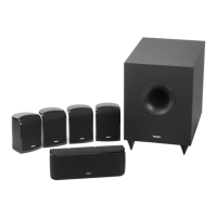
woofers in a 5.1 system. When using two subwoofers in
a 5.1 bass management system with the shown system
setup (fig 5), it is easy to see why the "One Sub/Two
Sub" feature is needed. The left signal is connected to
the left sub and the right signal is connected to the right
sub, and both subs need the center signal. The problem
now, is that a 12 dB gain in energy is coming from the
subwoofer. To obtain unity gain through the LCR we must
reduce the level of the signal of the Center channel pro-
gram material. This is obtained by selecting the "Two
Sub" switch position. This does not affect each individual
subwoofer’s mode of operation because there is only Left
or Right signal present at each unit respectively.
1/8” - 3.5 mm
Mono
For custom remote switches, follow schematic diagram.
 Loading...