Do you have a question about the Tappan TMV151FBA and is the answer not in the manual?
Details key electrical and physical specifications for the microwave oven, including power, frequency, and dimensions.
Essential safety checks including interlock, door closing, and component integrity before activating the microwave.
Procedures for ensuring proper alignment and integrity of critical microwave generation and transmission systems.
Mandates microwave leakage checks to ensure compliance with federal standards prior to releasing the oven.
Emphasizes adherence to manual procedures, Federal Standard 21 CFR, and performing emission checks.
Guidelines for instructing users on unsafe operation and notifying service centers about leakage exceeding limits.
Importance of restoring protective devices, ensuring proper grounding, and using correct AC power cords.
Warnings against defeating interlocks, handling static-sensitive devices, and connecting test instruments safely.
Warning against measuring high voltages and mandatory discharge of the high-voltage capacitor before servicing.
Extreme danger of working on energized high voltage circuits and prohibition of voltage measurement.
Reminds servicemen to remove watches and avoid touching wiring with uninsulated tools.
Lists essential accessories like glass tray, roller guide ring, coupler, hardware kit, and filters.
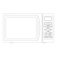
Identifies buttons for cooking modes, cooking time, power levels, and special functions like clock and timer.
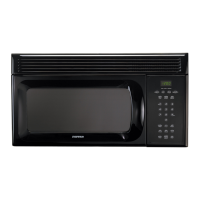
Labels external parts of the microwave oven, including door, window, handle, control panel, and grille.
Provides overall dimensions and visual representations of the oven's exterior design.
Details the process of mounting the bracket assembly to the wall for supporting the oven.
Specifies the load-bearing capacity and cabinet arrangement requirements for safe installation.
Explains the vent blower's function and user-replaceable cooktop and oven lights.
Describes the purpose and maintenance of reusable grease filters to protect the microwave from cooktop flames.
Instructions for removing the charcoal filter and the top grille for access to internal components.
Explains the automatic fan's function for heat protection and its operating behavior.
Step-by-step guide for safely removing the microwave oven from its wall mounting, requiring two people.
Steps for safely removing and replacing the high voltage transformer, including capacitor discharge.
Detailed instructions for replacing the magnetron, emphasizing careful handling and gasket placement.
Crucial reminder to ensure the RF anode gasket is in place and to perform a microwave leakage test after replacement.
Specific procedures for removing different parts of the door assembly, such as Door "C" and Door "E".
Instructions on how to remove the key door and its associated spring from the door assembly.
Guidelines for reassembling the door correctly and performing a microwave leakage test to prevent leaks.
Steps for replacing the fuse and identifies related switches that may need replacement if the fuse blows.
Instructions for replacing the turntable drive motor, including coupler reattachment and wiring connections.
Detailed instructions for removing and replacing the stirrer motor assembly, including disconnecting wires and screws.
Procedure for accessing and removing the stirrer and its cover from the wave guide assembly.
Steps for removing the control box and the Printed Circuit Board (PCB) assembly, including connector handling.
Guidance on replacing the window display and membrane keypad, including tips for careful removal and installation.
Procedures and expected resistance values for testing the high voltage transformer's primary and secondary windings.
Method for testing the low voltage transformer's continuity and checking its resistor readings.
Steps to check magnetron filament continuity and resistance to the case for diagnosing faults.
How to test the high voltage capacitor's continuity and resistance for shorts or opens.
Instructions for measuring the front-to-back resistance of the high voltage diode.
Procedures for testing the main and power control relays, including checking continuity after operation.
Detailed steps for adjusting primary, door sensing, and monitor switches, including gap confirmation.
Procedure for testing the run capacitor of the vent blower motor using an analog meter.
Steps to check the continuity of the blower motor windings for proper operation.
Instructions for removing the vent blower motor assembly from the oven.
Details the location and non-resettable nature of the oven cavity thermal cutout.
Explains the hood thermal cutout's role in protecting controls and provides removal steps.
Describes the bottom thermal cutout's safety function during fires and its removal process.
Explains the magnetron thermal cutout's purpose in preventing magnetron damage and its reset mechanism.
Detailed procedure for measuring magnetron output power using a water temperature rise test.
Method for checking heat distribution evenness using multiple water samples at different oven locations.
Step-by-step guide for measuring microwave energy leakage using a survey meter and water load.
Important notes on measurement techniques, probe handling, and the maximum allowable leakage limits.
Guidelines for recording leakage test results and the requirement for annual survey meter calibration.
Identifies causes and corrections for the oven not powering on or displaying any activity.
Lists potential causes and solutions when the control panel does not respond to input.
Addresses issues where the timer runs but the microwave function does not activate.
Troubleshooting steps for when the oven cannot initiate a timed cooking cycle.
Diagnoses problems related to low cooking power, fan motor operation, and oven non-responsiveness.
Provides solutions for loud buzzing noises and the turntable motor not rotating correctly.
Offers guidance on common problems like sparks, uneven cooking, and unexpected beeping sounds.
Lists specific error codes and their meanings for diagnosing faults.
Illustrates the main internal and external parts of the microwave oven in an exploded view.
Shows an exploded view specifically detailing the door and control panel components.
Catalog of key parts from item 1 to 48, including descriptions and quantities for service.
Continues the parts list, covering sub-assemblies and components from item number 49 to 100.
Lists further parts and assemblies from item 101 to 150, essential for repair and maintenance.
Lists the remaining parts from item 152 to 160, focusing on grilles and associated components.
Illustrates the power supply, control logic, and component interconnections in the main circuit.
Lists electrical parts related to power supply, relays, connectors, and displays with specifications.
Details semiconductor devices like diodes and ICs, along with passive components like capacitors and resistors.
Lists digital transistors, carbon resistors, and other passive components with their specifications.
Details various types of capacitors, thermistors, ceramic resonators, and PCB part numbers.
Depicts the power, vent motor, and lamp circuits, including thermal cutouts and relays.
Illustrates the high voltage transformer, magnetron, capacitor, and diode connections.
Visualizes the wiring harness connections for motors, switches, lamps, and filters, indicating wire colors.
Addresses customer queries regarding oven venting and unexpected automatic operation.
Provides solutions for heating inconsistencies, grounding issues, and turntable rotation anomalies.
Offers explanations and remedies for popping sounds during cooking, oven odors, and error code interpretations.
Guides on purchasing accessories and resolving issues with the display screen, such as power saving activation.
| Brand | Tappan |
|---|---|
| Model | TMV151FBA |
| Category | Microwave Oven |
| Language | English |