3. Checking the pickup actuator operation
Before loading the disc,
turn the power ON and check
that the pickup actuator moves up and down six times.
(If the pickup is not
at
inside on the disc, perform the
above operation after moving the pickup to the inside.)
4. Focus offset check
1. Connect the jitter meter
between
RF terminal of R423
on the
MAIN PCB
and
GND.
2. Play the track 1 of the test disc MCD-111.
and
check
that the jitter value is SOnsec or less.
(RF level ; 1 ±0.2 Vp-p)
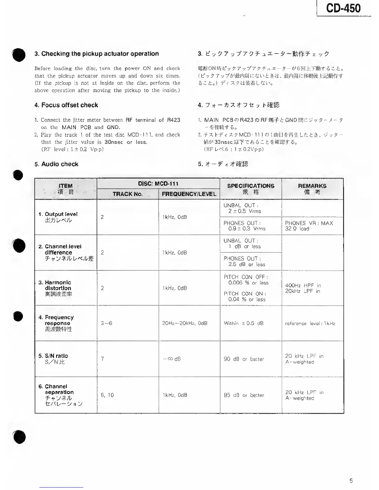
5. Audio check
3. f-:,
.y /7
97 y T’Atfirtja
Ih
fi
I
' i § IJ . l.adKl-fV-r
4. hSitS
1. MAIN
PCBO5R423
03RFfig^i GND Wlh
•>'
>
5-
-
-
9
2.
MCD-111 «llUiU«-li)'liLfcti.
vy9-
m<
30nsec
WT-C*) 5
C
i 6
=
(RF
UA./P
; 1
±0.2Vp-p>
ITEM
DISC: MCD-111
SPECIFICATIONS
REMARKS
II
S
TRACK No. FREOUENCY/LEVEL
m
IS
m m
1
.
Output level
2
IkHz,
OdB
UNBAL OUT
;
2 ± 0.5 Vrms
tli*
PHONES OUT
;
0.9 ± 0.3 Vrms
PHONES
VR ; MAX
32 Q
load
2. Channel level
difference 2 1kHz, OdB
UNBAL OUT
;
1
d6 or
less
PHONES OUT
:
2.5 dB
or
less
3.
Harmonic
diatortion 2
1 kHz.
OdB
PITCH
CON OFF
:
0.006
% or
less
PITCH CON ON :
0.04
% or less
400Hz HPF in
20kHz LPF in
4. Frequency
response
3~6
20Hz--20kHz,
OdB
Within ±
0.5 dB
reference
level ; IkHz
5. S/N ratio
S/Nit
7
-codB
90 dB or better
20 kHz LPF in
A- weighted
6. Channel
separation
t/fL/—
•>
3
y
8.
10 1kHz, OdB
85
dB or better
20 kHz LPF in
A-
weighted
5