Push the sanding belt along both of the transport rollers, starting from the back of the •
machine.
Push the clamping handle completely to the left. Now the sanding belt should be •
completely tight.
Turn the transport roller exactly in a right angle to the direction of the sanding belts with •
the use of the winged nut at the right roller. The direction of running of the belt is adjusted
correctly if the sides of the sanding belt are running parallel to the bearing plate.
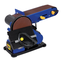
The sanding disc
Paper or “velcro” plates are used for the sanding disc. The standard diameter is 150 mm. The
plates are self adhesive.
Vertical placing of the sanding belt
For more flexibility of the sanding belt its bottom side can be used, because there is no bearing
plate. For an easy reach of this bottom side the sanding belt can be placed in vertical position.
Loosen the two nuts at the front of the sanding machine, around the left transport roller •
shaft, with the use of an open-end spanner.
Push the sanding belt up in the position desired.•
Fasten the two nuts again.•
The workpiece can now rest on the worktop instead of on the sanding belt;•
The work plate which is used for the sanding disc can now be pushed with the shaft into •
the hole of the machine frame, at the left side of the sanding machine.
Fasten the bolt at the back of the machine.•
The work plate can now be used as support for the sanding of the work piece against the •
sanding belt.
ASSEMBLY AND SPARE PARTS
Spare parts list
Position Description No.
126140 Guide roll 2
126141 Adjustment knob 9
126143 Drive roll + shaft 14
126142 Capacitor 17
126144 Motor pulley 29
126145 Sander disc 35 + 36
 Loading...