5 Operation
Interface options:
BF5, BF9, BF10,
BF100-1200
LN230, LN260,
LN265,
LN600-Serie
FP150, FP211,
FP213
GL20,
GL30, GL230,
GL265, GL400,
CR-Serie
TFS500
TFS1000
OEN150,
OEN155,
OEN700-Serie
Filter full x x x x x x
Filter full inverted x x x x x x
Start / Stop x x x x x x
Jumper run x x x x x x
Speed OK - x x x x x
Temperature fault - x x x x x
External speed control - x x x x x
Collective error - x x x x x
External cleaning activation - - x - - -
The connection assignments can be found in the description of interfaces in Section 8
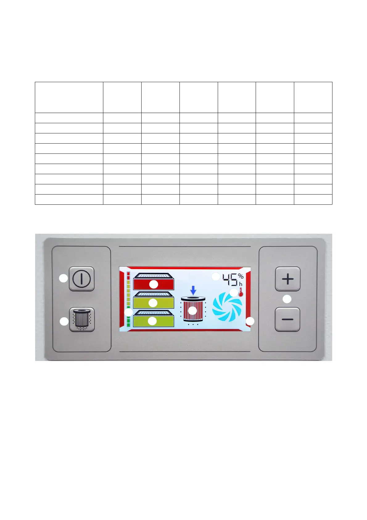
Front panel
The diagram shows the max. equipment for the system (if there is a fault) as an example.
Pos. 1: Run/Standby button Pos. 6: Filter cleaning status message
(only on systems with filter cartridge)
Pos. 2: Manual activation button
Filter cleaning
(only on systems with filter cartridge)
Pos. 7: Fault message display
Motor/Temperature
Pos. 3: Extraction level control Pos. 8: Power setting / operating hour meter display
Pos. 4: Filter saturation indicator
(shows the filter saturation for all filter stages installed
in the system together)
Pos. 9: System fault indicator
Pos. 5: Filter status indicator
68-236
 Loading...