16 TC2290 User Manual
5. Plug-in and Hardware Controls
Control of the TC2290 is done in the plug-in or optionally done using the
hardware unit (when you have purchased the DT version) . All primary
parameters of the 2290 are also accessible through the DT Desktop Controller.
These include parameters that control major parts of the eect, such as delay
time, modulation, preset changes, mix (via 'Special' control) and much more.
Secondary parameters that are needed less often are handled in the plug-in
window in its right section. These are parameters like modulation thresholds,
subdivision, preset save and more.
5.1 Primary Plug-in and Hardware Controls
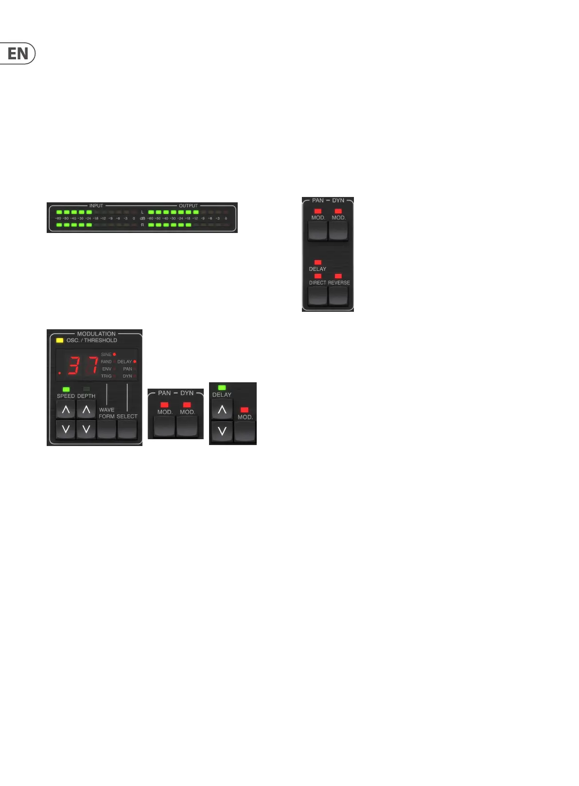
Meters
The meter section gives feedback about the incoming and outgoing audio
signals. The input level displays the audio as it enters the plug-in, and is not
aected by adjustments to the input level control or any other parameter.
The output meter is aected by the results of the eect as well as the output
level control parameter.
MODULATION
This section controls parameters of the modulation eects. Note that the
modulation is actually engaged with the MOD buttons located in the PAN,
DYN and DELAY sections.
Pressing the SELECT button scrolls through the parameter sets for the DELAY,
PAN and DYNAMICS, essentially selecting the focus of the other buttons in this
section. The types of modulation eects include:
• • Delay time modulations – chorus, anger, pitch, auto-doubling.
• • Pan position modulations – auto-panning of the direct signal, delay
signal, or both.
• • Dynamic modulation – tremolo, delay compressor/expander, ducking
and gating.
Each of these parameter sets consists of the following values:
WAVEFORM – determines the modulation waveform, between sine wave (SINE),
random wave (RAND), input signal envelope controlled (ENV), or input level
triggered (TRIG). The modulation target determines the function of ENV and TRIG.
SPEED – Pressing UP or DOWN once will bring focus to the SPEED parameter,
and additional presses will move the value by one step. The SPEED parameter
is shown in Hz (cycles per second). Depending on the modulation target,
when the ENV or TRIG Waveform is selected, the parameter controls the speed
from no eect to maximum eect. A setting of “1” means a ramp time of 1
second, whereas a setting of “5” means a ramp time of ⁄ of a second.
DEPTH – Pressing UP or DOWN once will bring focus to the DEPTH parameter,
and additional presses will move the value by one step. The DEPTH value is
displayed in percentage of maximum modulation.
Pressing the SPEED or DEPTH arrow keys will rst bring focus to that parameter,
which also allows a specic value to be entered on the KEYBOARD, followed by
the ENTER key. When either parameter is active, a green LED will ash above and
the display will show the current value.
The yellow OSC/THRESHOLD LED in the upper left corner of this section shows
modulation speed when using periodic modulations (SINE, RANDOM) and
indicates when the input level passes the threshold for ENV or TRIG eects.
PAN/DYN
Press either of the MOD buttons beneath the PAN and DYN labels to engage those
functions respectively. The red LEDs above each button indicate the on/o status.
The parameters for each eect are adjusted in the MODULATION section.
The DELAY/DIRECT button determines if the PAN eect is applied to the delay
signal only, the direct signal only, both or neither. This also applies to the static
pan set in the plug-in, so if neither DELAY nor DIRECT is lit, there is no panning
at all.
When neither DELAY nor DIRECT is lit, the delay signal is phase inverted in the
right channel. This is nice for creating wide chorus/anger eects, but may not
be desired for delay eects. To circumvent this, set PAN in the plug-in to 50,
disengage PAN MOD, and enable PAN DELAY (not DIRECT). This will give the same
result minus the phase inverse of right delay signal.
Note that whenever DIRECT is lit, the direct signal will rst be summed to mono
and then panned. When DIRECT is not lit, the direct signal will be stereo (if the
plug-in is a stereo instance).
The REVERSE button causes the selected Dynamic eect to function in an
opposite way. With the Waveform set to SINE or RAND, a tremolo eect is
achieved which produces a modulated increase/decrease in volume. When the
REVERSE button is activated, this creates a modulation that enhances delay
volume when direct volume is suppressed and vice versa.
With the Waveform set to ENV or TRIG, the REVERSE button changes the usual
Compression/Ducking eects into Expansion/Gating eects.
 Loading...