EasyManua.ls Logo

TCL LCD20W5HE User Manual

TCL LCD20W5HE
87 pages
To Next Page IconTo Next Page
Page #1 background imageLoading...
Page #1 background image
20 LCD TV TCL LCD20W5HE
1
Service
Service
Service
TABLE OF CONTENTS
Description Page Description Page
SAFETY NOTICE
ANY PERSON ATTEMPTING TO SERVICE THIS CHASSIS MUST FAMILIARIZE HIMSELF WITH THE
CHASSIS AND BE AWARE OF THE NECESSARY SAFETY PRECAUTIONS TO BE USED WHEN SERVICING
ELECTRONIC EQUIPMENT CONTAINING HIGH VOLTAGE.
Table Of Contents.......……..............................…........1
Revision List.…........................................……......2
Important Safety Notice.……..................……......3
1.General Specifications..............................………........4
2.Operating Instructions………..…………………….......5
2.1.The Use of Remote Control…................……...........5
2.2.To Use the Menu………..............................…...........7
2.3.LCD TV Description…….…..............……...............15
2.4.Interface Connector……............................…...........15
3.Precautions and Notices…............……………............16
3.1.Assembly Precaution…............………….................16
3.2.Operating Precaution…………...........................16
3.3.Storage Precaution…......………………..................16
3.4.High Voltage Warning.…..........…………................16
4.Input/Output Description……..…………… ...........17
4.1.D-SUB Connector……...…………………....….......17
4.2.Factory Preset Display Modes……………..….......18
5.Front Panel Control Knobs…....................................18
6.Repair Flow Chart…….............................................19
7.Mechanical Instructions……………................25
8.PCB Layout..………….......................................29
8.1.Main Board……….....…….................................29
8.2.Power Board…...………...................................32
8.3.Tuner Board…………........................................34
8.4.IR Board……………….......................................35
8.5.Key Board………………......................................35
8.6.Headphone Board………..................................36
9.Block Diagram………………..............................37
10.Schematic Diagram………………...............…38
10.1.Main Board.............................................38
10.2.Power Board....……....................................51
10.3.Tuner Board....……....................................52
11.Exploded View………..….......................................56
12.BOM………………………………………….............57
CAUTION: USE A SEPARATE ISOLATION TRANSFOMER FOR THIS UNIT WHEN SERVICING
Question and Answer IconNeed help?

Do you have a question about the TCL LCD20W5HE and is the answer not in the manual?

TCL LCD20W5HE Specifications

General IconGeneral
BrandTCL
ModelLCD20W5HE
CategoryLCD TV
LanguageEnglish

Summary

Revision History

First Version Release Details

Records the initial release of the service manual.

Crucial Safety Precautions

Laser Radiation Exposure Warning

Advises caution regarding laser radiation when servicing.

ESD and Handling Safety Guidelines

Procedures to prevent electrostatic discharge damage to components.

1. General Specifications Overview

LCD Panel and Display Details

Covers screen size, resolution, brightness, contrast, and response time.

TV Functions and Input Interfaces

Details TV standards, sound, video, and PC input specifications.

Power and Environmental Requirements

Specifies power supply, consumption, operating, and storage conditions.

2. Operating Instructions Guide

Remote Control Usage Explained

Describes the functions of each button on the remote control.

Teletext Service Access and Use

Information on accessing and navigating Teletext pages.

Menu System Navigation and Adjustments

Guide to accessing and adjusting picture, audio, and other settings.

PIP/PAP Mode Configuration

Steps for setting up Picture-in-Picture display modes.

Channel Tuning and Setup Procedures

Instructions for automatic and manual channel scanning.

Input Source Selection Methods

Procedures for selecting TV, AV, and PIP/PAP input sources.

System Setup Menu Options

Configuration of language, timers, and display preferences.

PC Mode Settings and Optimization

Guide to optimizing picture settings for PC input.

2.3 LCD TV System Overview

Internal Component Identification

Description of main internal boards like main, power, and tuner.

2.4 External Interface Connectors

Lists and describes all available external input/output ports.

3. Precautions and Notices

3.1 Assembly and Handling Precautions

Guidelines for safely assembling and handling the LCD panel.

3.2 Operating and Storage Guidelines

Advice for proper TV operation and storage conditions.

3.4 High Voltage Safety Warning

Critical warning about high voltage in the power board's inverter.

4. Input/Output Descriptions

4.1 D-SUB Connector Pinout

Detailed pin assignment for the 15-pin D-SUB connector.

4.2 Factory Preset Display Modes

Table of factory-configured display modes and timings.

5. Front Panel Controls

Description of Front Panel Buttons

Explains the function of each button on the TV's front panel.

6. Repair Flow Charts

6.1 No Power Troubleshooting Guide

Step-by-step diagnosis for no-power issues.

6.2 Start-up Failure (Yellow LED)

Troubleshooting for failure to start with a yellow LED indicator.

6.3 No Display (Green LED)

Diagnostic steps for no display with a green LED.

6.4 Abnormal Display Troubleshooting

Flowchart for resolving various display anomalies.

6.5 No Sound Troubleshooting

Diagnostic guide for resolving audio output problems.

7. Mechanical Instructions

Preparation and Stand Removal

Steps for preparing the unit and removing the stand.

Cover and Shield Removal Procedures

Guidance on removing back cover, shields, and front panel.

Board and Frame Disassembly

Steps for removing internal boards and the main frame.

8. PCB Layouts and 9. Block Diagram

8.1 Main Board PCB Layout

Detailed component layout for the main circuit board.

8.2 Power Board PCB Layout

Component layout for the power supply board.

8.3 Tuner Board PCB Layout

Component layout for the TV tuner board.

9. System Block Diagram

Visual representation of component interconnections and signal flow.

10. Schematic Diagrams

10.1 Main Board Schematic

Detailed circuit diagram for the main board.

10.2 Power Board Schematic

Circuit diagram for the power supply board.

10.3 Tuner Board Schematic

Circuit schematic for the TV tuner board.

Audio Decoder Schematic

Schematic for the audio decoder IC (MSP3410G).

11. Exploded View and 12. BOM List

11. Product Exploded View

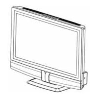
Illustration of all TV parts for assembly reference.

12. Bill of Materials (BOM)

Comprehensive list of all components and part numbers.

Related product manuals