w
At
the drive
shaft
side,
an
oil seal is press-fitted into the
pump
body to provide
oil tightness performance.
Oil
tightness
between
the
pump
body
and
the
pump
cover
is
secured
with
a
packing
of
a
special shape,
G
w
Q
CONTROL
VALVE
11-1
-2.
The control
valve
consists
of
an
inlet section,
two
plunger sections
and
an
outlet
section,
all
of
which are
assembled
with three bolts. The
two
plunger sections are
used
for lift and tilt circuits, respectively.
The plunger section for the lift circuit is a single-acting type:
when
the spool is
drawn
out, oil flows from the port
A
to the lift cylinders
and
when
the spool is
pushed in, the oil flows out of the lift cylinders and
passes
through the port
B
and
control
valve
back
to the oil tank.
The tilt circuit plunger section is of double-acting type.
With
the spool
drawn
out, the oil flows
from
the
port
A
to
'the
cap side
of
the tilt cylinders,
while
the oil
in the tail side
of
the cylinders returns through the port
B
and
control
valve
to the
tank.
When
the spool is pushed
in,
the
flow
becomes reversed.
The plunger section
for
the tilt circuit has a built-in tilt-lock
valve.
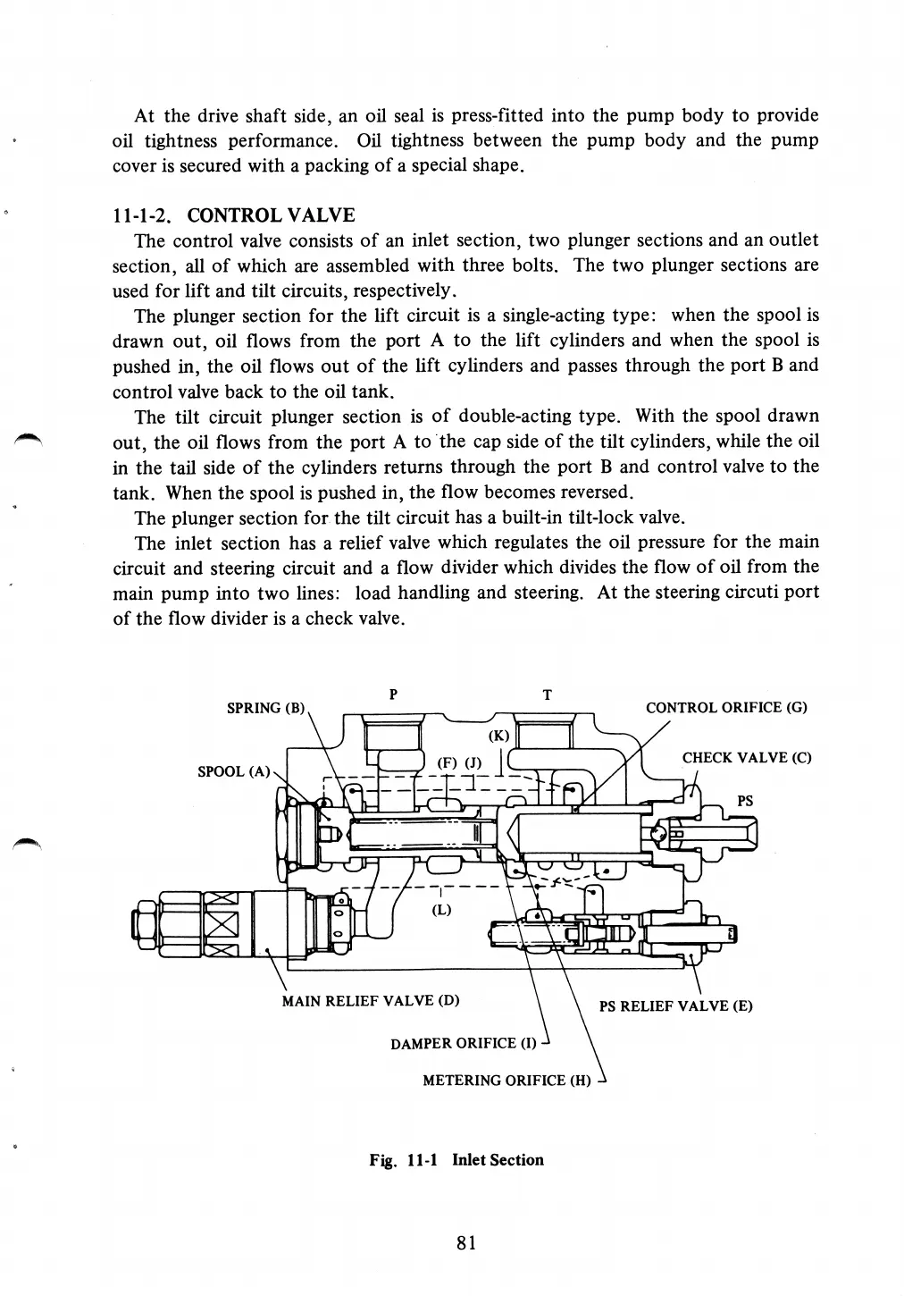
The inlet section has a relief
valve
which regulates the oil pressure for the main
circuit and steering circuit and a
flow
divider which divides the flow of oil from the
main pump into
two
lines: load handling
and
steering.
At
the steering
circus
port
of the
flow
divider is a check
valve.
P
SPRING
(B)
SPOOL
(A) \
I
i
5
g
I
s
I
V
CONTROL
ORIFICE
(G)
\
| (F) (J)
_.in
-»
I( b
,{
..____
(L)
1(
,5
iiwri
v
("r"
H
-M
II
`
u.;
.
*,¢
E"
MQ
Ills*»l
nu!
'L
l
CHECK
VALVE
(c)
PS
_
:n
I
l
\
I
it
MAIN
RELIEF
VALVE
(D)
PS
RELIEF
VALVE
(E)
DAMPER
ORIFICE (I) -
METERING
ORIFICE
(H)
W
Fig.
ll-l
Inlet
Section
81