Do you have a question about the TDI UltraFLEX HD and is the answer not in the manual?
Warning about high touch current and the necessity of earth connection.
Details the input voltage, frequency, and current ratings for the PDU.
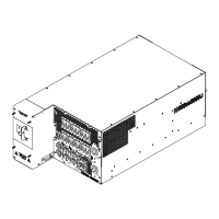
Explains the installation requirements and weight of the PDU.
Describes the required AC input specifications and safety procedures.
Details the AC output connections and their corresponding breakers.
Explains the DC output and fan power connections.
Explains the EMO loop functionality and connector usage for safety shutdown.
Describes the SMC connector and its pinout for system control.
Details the external indicator connector and its pinout for status signals.
Warning about high touch current and the necessity of earth connection.
Specifies system input voltage, frequency, current, and ambient operating conditions.
Explains the installation requirements and weight of the PDU.
Describes the required 3-phase AC input and safety precautions for wiring.
Lists AC output connectors, their circuit breakers, and ratings.
Explains the DC output and fan power connections.
Explains the EMO loop for emergency shutdown and its connectors.
Provides pinout details for the SMC interface connector J72.
Details the pinout for the external indicator connector J71.
Step-by-step procedure for turning on the system.
Instructions for turning on the EMO breaker CB2 for system initialization.
Procedure to energize the AC input and check the AC Available LED status.
Steps to turn on the AC input breaker CB1 and check the Main Power On LED.
Procedure for connecting and turning on AC loads via the load breakers.
Instructions to turn on the fan breaker CB10 for fan power.
Steps to turn on the power supply AC input breaker CB9.
Procedure for enabling the 48V DC bus via the SMC controller.
Readiness check for system testing after operational setup.
Provides an overview of PDU functionality, specifications, and connector pinouts.
Details the AC input configuration, voltage, and frequency.
Describes the 24V EMO supply and its protection breaker.
Explains the 3-phase AC input breaker and its UVR functionality.
Details the AC distribution on the front panel and load balancing.
Explains facility, frame, and DC grounding connections.
Details the 48V DC output and fan power distribution.
Explains the EMO loop mechanism for shutting down the PDU and lists EMO connectors.
Details how monitoring and control are achieved via the interface PCB.
Specifies the operating voltage range for the power supply and AC input.
Details the acceptable frequency range for the AC input.
Describes the lockout feature for securing the AC input breaker.
Lists specifications for AC distribution connectors.
Details the 115VAC output of AC outlets J52/J53.
Provides pinout details for the CDU connector J59.
Details internal AC wiring for EMO supply and power supplies.
Explains facility ground connection near the input breaker.
Describes the location of the frame ground connection.
Explains the DC return connection to chassis ground.
Provides DC output ratings for main output, fans, and power control.
Describes the location and spacing of the main 48V DC output bus bars.
Details fan connectors and the protective circuit breaker CB10.
Provides pinout details for the Testhead Fan connector J46.
Provides identical pinout details for Cabinet Fan connectors J47 and J48.
Provides pinout details for the Expansion Cabinet power connector J49.
Describes the 48V DC output voltage variation with load.
Shows interface PCB connections, including SMC connector J72.
Explains the 48V DC enable signal from the SMC controller.
Describes the common 48V DC power fault signal and its causes.
Details the DC current monitor signal provided to the SMC controller.
Lists LED indicators and alarm output signals on the interface PCB.
Provides pinout for the alarm output connector J71.
Explains the AC Available signal and LED indicator.
Explains the Main Power On signal and LED indicator.
Explains the 48V DC On signal and LED indicator.
Describes the LED indicators for power supply status.
Locates test points on the interface PCB for troubleshooting.
Details the thermostat's function and location for temperature shutdown.
Summarizes AC input specifications including voltage, frequency, and current.
Summarizes AC distribution connectors, breakers, voltage, and frequency.
Summarizes DC output connectors, breaker ratings, and max current.
Lists PDU dimensions, weight, and individual power supply weight.
Details operating and storage temperature, humidity, and ambient noise.
Provides contact information for sales support and facility hours.
Contact information for service related to GFS and general customers.
Details TDI's 24-hour technical service support and warranty procedures.
Explains how the document is supplied to Teradyne for review and editing.
| Brand | TDI |
|---|---|
| Model | UltraFLEX HD |
| Category | Industrial Equipment |
| Language | English |