The PIG-SIG® IV Scraper Passage Indicator is a device designed to detect the passage of a pig or sphere through a pipeline. It is available in various combinations of operation, materials, and construction, depending on piping requirements.
Function Description
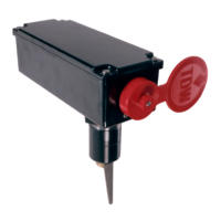
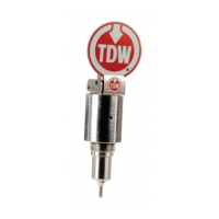
The primary function of the PIG-SIG® IV is to provide a clear indication when a pipeline scraper or pig passes a specific point. This is achieved through a signaling mechanism that can include a flag indicator, an electrical indicator, a combination flag and electrical indicator, or a rotary cap indicator. The device is designed to be weatherproof and corrosion-resistant, with housings manufactured from space-age plastic for durability and weather resistance. The flag indicator offers high visibility from the air or ground.
Important Technical Specifications
The PIG-SIG® IV is designed for installation on a pipeline using a carbon steel nipple, which is manufactured from easily weldable material. The plug assembly can be installed on or removed from a pressured pipeline using a TDW T-101 or T-101b Drilling Machine and accessories.
-
THREAD-O-RING Nipple Material Specification:
- Size & Grade: 2 NPS XXS, ASTM A 333 Grade 6 seamless steel pipe.
- Tensile Requirements: 35,000 psi SMYS – 60,000 psi SMTS.
- Impact Requirements: 13 ft-lbf min Avg 3 Specimens, 10 ft-lbf min One Specimen Only. Impact Temperature: -50 °F.
- Chemical Composition Percentage: Carbon: 0.30 max; Manganese: 0.29-1.06; Phosphorus: 0.025 max; Sulfur: 0.025 max; Silicon: 0.10 min.
- Test Report: Certified test reports furnished per ASTM A 530.
-
Pressure-Temperature Ratings (for PIG-SIG IV Scraper Passage Indicator THREAD O-RING NIPPLE, excluding allowance for corrosion):
- B31.3:
- -50°F: 3743 psi
- -20 to 250°F: 3743 psi
- 300°F: 3159 psi
- 350°F: 3159 psi
- 400°F: 3072 psi
- 450°F: 3072 psi
- 500°F: 2985 psi
- B31.4:
- -50°F: 3743 psi
- -20 to 250°F: 3743 psi
- 300°F: 3620 psi
- 350°F: 3493 psi
- 400°F: 3369 psi
- 450°F: 3246 psi
- 500°F: 2985 psi
- B31.8:
- -50°F: 3120 psi
- -20 to 250°F: 3120 psi
- 300°F: 3017 psi
- 350°F: 2911 psi
- 400°F: 2808 psi
- 450°F: 2246 psi
- 500°F: 2246 psi
-
Electrical Specifications (for Electrical Indicator Switch):
- Double-pole, 2 N.O., 2 N.C. Momentary (¾-inch conduit).
- Electrical Ratings: 10 amps continuous carry. Circuits on any one pole must be the same polarity.
- MICRO SWITCH®: Weather-sealed explosion-proof switch BXP4L is designed specifically for use in hazardous location applications. The switch enclosure is sealed for protection against corrosion, water, dust, and oil as defined in NEMA 1, 3, 4X, 6, 7, 9 and 13 and IP67.
- Switch Enclosure Meets: European Hazardous Locations Designation: EExd IIC T6 category II 2 GD, SIRA 00ATEX 1037X.
- Operating Temperature Range: -40°F (-40°C) to 158°F (70°C).
- Switch Housing: Epoxy coated Aluminum and Zinc with Fluor silicone seals.
-
AC Volts – Pilot Duty: 600 VAC, 720 VA:
- Circuitry | VAC | Make | Break
- Single-Pole | 240 | 15 | 1.5
- Double-Pole Double-Throw | 480 | 7.5 | 0.75
- Double-Pole Double-Throw | 600 | 6 | 0.60
-
DC Volts – Pilot Duty: 240 VDC, 30 Watts:
- Circuitry | VDC | Inductive | Resistive
- Single-Pole | 24 | 10 | 10
- Double-Pole Double-Throw | 120 | 0.25 | 0.8
- Double-Pole Double-Throw | 240 | 0.15 | 0.4
-
NEMA Types (Reference Standards):
- Non-Hazardous Locations:
- Type 1: Indoor use, degree of protection against contact with enclosed equipment.
- Type 3: Outdoor use, degree of protection against windblown dust, rain, sleet, and external ice formation.
- Type 4: Outdoor use, degree of protection against windblown dust and rain, splashing water and hose-directed water.
- Type 4X: Indoor or outdoor use, degree of protection against corrosion, windblown dust and rain, splashing water and hose-directed water.
- Type 6: Indoor or outdoor use, degree of protection against the entry of water during occasional temporary submersion at a limited depth.
- Type 13: Indoor use, degree of protection against dust, spraying of water, oil and non-corrosive coolant.
- Hazardous Locations:
- Type 7: Use in locations classified as Class I, Groups B, C, or D as defined in the National Electrical Code.
-
Group B: Atmospheres containing hydrogen manufactured gas.
-
Group C: Atmospheres containing diethyl ether, ethylene or cyclopropane.
-
Group D: Atmospheres containing gasoline, hexane, butane, naphtha, propane, acetone, toluene or isoprene.
- Type 9: Use in locations classified as Class II, Groups E, F, or G, as defined in the National Electrical Code.
-
Group E: Atmospheres containing metal dust.
-
Group F: Atmospheres containing carbon Hack, coal dust or coke dust.
-
Group G: Atmospheres containing flour, starch or grain dust.
-
Conforming International Standard:
- Type of Protection | NEMA | IEC
- Rain Tight | Type 3 | IP-63
- Water Tight | Type 4 | IP-65
- Submersible | — | IP-67
- Oil Tight/Dust Tight | Type 13 | —
Usage Features
The PIG-SIG® IV is designed for ease of installation and operation, with several configurations to suit various pipeline needs:
- Installation: Involves pre-cut hole tapping, welding instructions, and tapping the line. The THREAD-O-RING nipple is installed over a pre-cut opening in the pipe, or the opening may be cut using a drilling machine with a 1-7/16-inch drill. The nipple must be coaxial with the hole cut in the pipe to within 1/32-inch.
- Plug Installation: The plug can be unidirectional or bi-directional. For unidirectional plugs, the arrow on top of the plug should point in the direction of flow. For bi-directional plugs, arrows should align with the pipeline axis. The plug is inserted into the nipple, and the distance from the valve face to the top of the tapping fitting is measured to ensure correct positioning.
- Indicator Installation: This involves installing the drive sleeve into the plug, followed by the spring. The housing/cap assembly is then threaded onto the nipple.
- Trigger Mechanism: The trigger is positioned by placing the cam on the shaft, ensuring it is inserted between the legs of the spring. The cam position is crucial for proper trigger operation.
- Flag and/or Electrical Switch Indicator: The device can be configured with a flag indicator, an electrical switch indicator, or both. The flag provides a visual indication, while the electrical switch can be integrated into control systems.
- Extended Indicator Installation: For applications requiring an extended indicator, a thread extension is fitted onto the nipple.
Maintenance Features
Regular maintenance is crucial for the reliable operation of the PIG-SIG® IV.
-
Preventative Maintenance Checklist:
- Flag Position: Check if the flag is positioned properly. When looking at the TDW flag, the flag should be turned down ½ turn clockwise. This is the proper position before Pig passage. Once the Pig has passed, the flag should be standing up. The flag will need to be reset before the next Pig passage.
- PIG-SIG Wires: If the PIG-SIG is electrical, check if the indicator properly wired.
- Spring Retainer and Cam: Check the set screws in the spring retainer and cam. Ensure they are tightened to the shaft.
- Lower and Upper Torsion Spring: Loosen the two set screws in the spring retainer and the top torsion spring. Loosen the two set screws in the cam.
- Shaft Rotation: Using a screwdriver, turn the shaft in the center of the cam. The shaft should rotate freely at least 90 degrees.
- Plug Trigger Position: Check if the plug trigger is positioned properly. For uni-directional plugs, turn the shaft counterclockwise until it comes to a stop. Tighten the two set screws in the cam. This is the position the trigger should be in before the Pig passes. The springs will reset the trigger after the Pig passes.
- Plug Alignment: Check if the plug is aligned with the pipeline axis. The arrows stamped on top of the plug should align with the pipeline. For a uni-directional plug, the arrows should point in the direction of flow.
- Drive Sleeve: Check if the drive sleeve is installed in the plug. It should look like a 3/8 socket.
- Set Screw: Check if the set screw in the top of the plug is tightened into the nipple. There are two small holes inside the square hole of the plug. One of these has a set screw in it which needs to be tightened into the wall of the nipple, so the plug does not turn during installation or operation.
- Shaft Inside Plug: Check if the shaft inside the plug turn ¼ turn. You can use a ½-inch hex key (Allen wrench) and the drive sleeve to check this.
- Shaft Rotation: Check if the shaft turn freely and smoothly.
-
Removing and Checking O-ring: After retracting the plug, the O-ring should be removed and checked for damage.
-
Boring Bar Retraction: Fully retracting the boring bar by turning the feed tube counterclockwise is essential. Do not permit the boring bar to turn, or the plug will unthread.
-
Plug Alignment Check: After removing the drilling machine and tapping valve, check the plug to ensure it is aligned.
-
Bleeder Valve Operation: The bleeder valve should be opened to release pressure and then closed after the air is completely purged.
-
Locking Cap: Install the locking cap to secure the feed tube and boring bar.
The manual provides detailed instructions and diagrams for installation, operation, and maintenance, emphasizing safety precautions throughout the process. It also includes a list of hex keys (Allen wrenches) required for various adjustments.