1 of 4
© 2016 TE Connectivity family of companies
All Rights Reserved
*Trademark
TE Connectivity, TE connectivity (logo), and TE (logo) are trademarks. Other logos, product, and/or company names may be trademarks of their respective owners.
PRODUCT INFORMATION
1-800-522-6752
This controlled document is subject to change.
For latest revision and Regional Customer Service,
visit our website at www.te.com.
Instruction Sheet
408-9930
08 FEB 16 Rev G
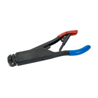
Figure 1
1. INTRODUCTION
This instruction sheet provides application and maintenance procedures for PRO-CRIMPER III Hand Crimping
Tool Frame Assembly 354940-1, shown in Figure 1. The tool is designed to accept interchangeable die
assemblies for crimping various types of products.
NOTE
In most cases, the tool frame assembly is provided with a specific set of dies and is considered a component part of a
crimping assembly. Refer to the appropriate instruction sheet packaged with the hand tool and die assembly or with the
separate die assembly for information regarding crimping procedures, crimp height inspection, and die gaging.
Read these instructions thoroughly before installing dies and using the tool frame.
Reasons for reissue of this instruction sheet are provided in Section 7, REVISION SUMMARY.
2. DESCRIPTION
The tool frame consists of two crimping jaws, an adjustable ratchet, spring-actuated handles, two die retaining
screws, and an emergency ratchet release. The slotted design of the tool jaws permits easy installation and
removal of dies. The adjustable ratchet allows handle pressure to be set for optimum die performance.
Cumulative Trauma Disorders can result from the prolonged use of manually powered hand tools. Hand tools are intended for occasional use and low
volume applications. A wide selection of powered application equipment for extended-use, production operations is available.
PRO-CRIMPER* III Hand Crimping
Tool Frame Assembly 354940-1
Emergency Ratchet
Release
The PRO-CRIMPER III Hand Crimping Tool is a “Commercial" grade tool and is
designed primarily for field installation, repair, maintenance work, or prototyping in
industrial, commercial, or institutional applications. Product crimped with this tool will meet
the crimp height requirement for hand tools in the appropriate Application Specification
(114-series), but may not comply with other feature parameters of the specification.
TE Connectivity offers a variety of tools to satisfy your performance requirements.
For additional information, contact PRODUCT INFORMATION at 1-800-522-6752.