EasyManua.ls Logo

TE Connectivity MATE-AX 2335290-1 - User Manual

TE Connectivity MATE-AX 2335290-1
11 pages
Print Icon
To Next Page IconTo Next Page
Loading...
Instruction Sheet
1 of 11
© 2021 TE Connectivity Ltd. family of companies.
All Rights Reserved.
TE Connectivity, TE connectivity (logo), and TE (logo) are trademarks. Other logos, product, and/or company names may be trademarks of their respective owners.
PRODUCT INFORMATION
1-800-522-6752
This controlled document is subject to change.
For latest revision and Regional Customer Service,
visit our website at
www.te.com.
408-35051
24 JUN 2021 Rev A
PROPER USE GUIDELINES
Cumulative trauma disorders can result from the prolonged use of manually powered hand tools. Hand tools are intended for occasional
use and low-volume applications. A wide selection of powered application equipment is available for extended-use production operations.
The SDE-SA hand tool is a commercial-grade tool. Product crimped with this tool meets the wire barrel crimp height requirement for hand
tools in the appropriate 114 application specification, but might not comply with other feature parameters of the specification.
Figure 1: MATE-AX Hand Tool Assemblies
1
2
3
1
Inner Ferrule Tool
2
Center Contact Tool
3
Outer Contact Tool
Table 1: MATE-AX hand tool kits
Crimping
tool
Cable
Terminal
part numbers
Strip length
2335290-1
RTK031
2298126-1
Refer to TE
Specification
114-94413
2335290-2
RG174 with foil
2298509-1
2335290-3
RG174 without foil
2335280-1
RTK031
2298121-1 (Socket)
2298125-1 (Pin)
2335280-2
RG174
2298496-1 (Socket)
2298508-1 (Pin)
2335300-1
RTK031
2298116-1 (Socket)
2298123-1 (Pin)
N/A
2335300-2
RG174
2298494-1 (Socket)
2298506-1 (Pin)
MATE-AX Hand Tool Assemblies
Question and Answer IconNeed help?

Do you have a question about the TE Connectivity MATE-AX 2335290-1 and is the answer not in the manual?

Overview

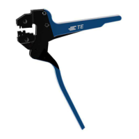
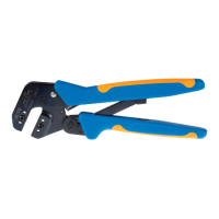
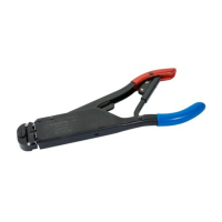
The MATE-AX Hand Tool Assemblies are manually powered tools designed for crimping terminals in low-volume applications. These tools are intended for occasional use, and for extended-use production operations, powered application equipment is recommended to avoid cumulative trauma disorders. Products crimped with these tools meet the wire barrel crimp height requirements for hand tools as specified in the relevant 114 application specification, though other feature parameters may not be met.

Each MATE-AX Hand Tool Assembly consists of an SDE-SA Frame Assembly (Instruction Sheet 408-8851) and a specific die assembly. The tools are categorized into three main types: Inner Ferrule Tool, Center Contact Tool, and Outer Contact Tool, each designed for particular crimping tasks.

Technical Specifications:

The tools are designed to crimp specific terminal part numbers and cable types, with corresponding crimp height specifications:

  • Inner Ferrule Tools:

    • 2335290-1 (Inner Ferrule Tool (RTK031)): For RTK031 cable, with a ferrule part number 2298126-1, and a crimp height of 2.80±0.04 mm.
    • 2335290-2 (Inner Ferrule Tool (RG174 with foil)): For RG174 with foil cable, with a ferrule part number 2298509-1, and a crimp height of 2.20±0.03 mm.
    • 2335290-3 (Inner Ferrule Tool (RG174 without foil)): For RG174 without foil cable, with a ferrule part number 2298509-1, and a crimp height of 2.15±0.03 mm.
    • Strip length for inner ferrule tools should refer to TE Specification 114-94413.
  • Center Contact Tools:

    • 2335280-1 (Center Contact Tool (RTK031)): For RTK031 cable, with ferrule part numbers 2298121-1 (socket) and 2298125-1 (pin), and a crimp height of 0.69±0.03 mm.
    • 2335280-2 (Center Contact Tool (RG174)): For RG174 cable, with ferrule part numbers 2298496-1 (socket) and 2298508-1 (pin), and a crimp height of 0.53±0.02 mm.
  • Outer Contact Tools:

    • 2335300-1 (Outer Contact Tool (RTK031)): For RTK031 cable, with ferrule part numbers 2298116-1 (socket) and 2298123-1 (pin), and a crimp height of 3.55±0.04 mm.
    • 2335300-2 (Outer Contact Tool (RG174)): For RG174 cable, with ferrule part numbers 2298494-1 (socket) and 2298506-1 (pin), and a crimp height of 3.00±0.03 mm.
    • Strip length for outer contact tools is N/A (not applicable) in the provided table.

Usage Features:

The tool frame incorporates two jaws, a handle, a ratchet adjustment wheel, and an emergency ratchet release. The die set consists of a crimper (upper die) and an anvil (lower die), secured in the tool frame by die retaining pins and screws.

  • Ratchet Mechanism: The tool features a ratchet that ensures a complete crimping cycle by preventing release until the handles are fully closed. An adjustment wheel allows control over the handle pressure exerted on the dies during crimping. The dies are designed to bottom out before the ratchet releases, ensuring maximum tensile performance of the crimp.
  • Die Set Installation and Removal: The process involves opening the tool handles, removing die retaining screws, positioning the wire anvil and insulation anvil (chamfered sides and marked surfaces facing outward) in the moving jaw, inserting die retaining pins, and securing with the short die retaining screw. The wire crimper and insulation crimper are similarly positioned in the stationary jaw and secured with the long die retaining screw. The tool handles are then carefully closed to align the anvil and crimper, engaging the ratchet, before tightening the retaining screws. A locator assembly is then placed over the long screw and secured with a nut, allowing the locator blade to slide. Disassembly is the reverse process.
  • Crimping Procedure:
    • Inner Ferrule Tools: After selecting the correct cable and stripping the jacket (without nicking or cutting braid strands), the tool is held with the wire side facing the user. A section of strip product is inserted into the floating shear and advanced to center the ferrule over the anvil, assisted by a ball detent. The stripped cable is then positioned in the floating shear, seating the stripped jacket against the locating surface. The tool is fully cycled until the ratchet releases. The crimped ferrule is then removed and inspected for crimp height and position.
    • Center Contact Tools: Similar to inner ferrule tools, the tool is held with the wire side facing the user, and strip product is inserted into the floating shear to center the ferrule over the anvil. The prepared cable, with the crimped ferrule, is then positioned in the floating shear, aligning the ferrule's gap to the outer insulation in the locating feature and the seam in the ferrule with the mark on the floating shear. The tool is fully cycled, and the crimped contact is inspected.
    • Outer Contact Tools: The tool is held with the wire side facing the user. The prepared cable is inserted into the outer contact sub-assembly. The terminal lock is opened, and the contact sub-assembly is positioned. The terminal lock is then released to fix the sub-assembly. The tool is fully cycled, and the crimped contact is inspected.
  • Crimp Height Adjustment: The tool includes a crimp adjustment feature. Before use, the crimp height should be verified using a micrometer with a modified anvil (crimp-height comparator). If the crimp height is incorrect, the ratchet can be adjusted. If the crimp height is larger than recommended, the ratchet wheel adjustment screw is removed, and the adjustment wheel is rotated counterclockwise (+) to a higher setting. If smaller, it's rotated clockwise (-) to a lower setting. If the crimp height cannot be conformed, the tool or die set must be replaced.

Maintenance Features:

  • Cleaning: Dust, moisture, and other contaminants should be removed with a clean soft brush or lint-free cloth. Objects that could damage the dies or tool should not be used. All lubrication and accumulated film can be removed by immersing the dies in a suitable commercial degreaser.
  • Storage: When not in use, the handles should be kept closed to prevent objects from lodging in the dies. The tool should be stored in a clean, dry area.
  • Inspection: Regular visual inspection of the tool and dies is recommended to check for wear or damage. Die retaining screws should be properly secured. The crimping chambers of the die assembly should be inspected for flattened, chipped, worn, or broken areas. Damaged or abnormally worn dies should be replaced.
  • Replacement and Repair: If dies are damaged or excessively worn, they must be replaced. Parts can be ordered through a TE representative, via TE.com (Shop TE link), by calling 800-522-6752, or by writing to CUSTOMER SERVICE (038-035), TE CONNECTIVITY CORPORATION, PO BOX 3608, HARRISBURG PA 17105-3608. For customer repair services, call 800-522-6752.
  • Damaged Product: Damaged products should not be used. If a damaged contact is evident, it should be replaced, and contacts should not be re-terminated.

TE Connectivity MATE-AX 2335290-1 Specifications

General IconGeneral
BrandTE Connectivity
ModelMATE-AX 2335290-1
CategoryPower Tool
LanguageEnglish

Related product manuals