409-10204
Rev G
Figure 9
4. Set the crimp height and insulation crimp discs so that the letters and numbers on the applicator pad
align with the front pad on the ram post adapter.
5. If the applicator is an air-feed type, make sure the front door cover is closed, then connect the airlines
to the valves located on the back of the machine.
NOTE
Quick Disconnect Coupling PN 23238-1 is required to run air-feed applicators.
6. Adjust the reel support for side-feed or end-feed product, depending on the applicator being used.
7. Mount the terminal strip guide on the left sheet metal guard for side-feed product, or on the right sheet
metal guard for end-feed product, depending on the applicator being used.
8. Mount the terminal reel on the reel support. Thread the terminal strip through the guard and into the
applicator according to the instruction sheet included with the applicator. If necessary, adjust the
lubricator bowl.
9. Align the product reel to the applicator by adjusting the reel flanges.
10. Close the guard.
NOTE
The guard door must be closed in order to operate the machine. See paragraph 4.4.C.
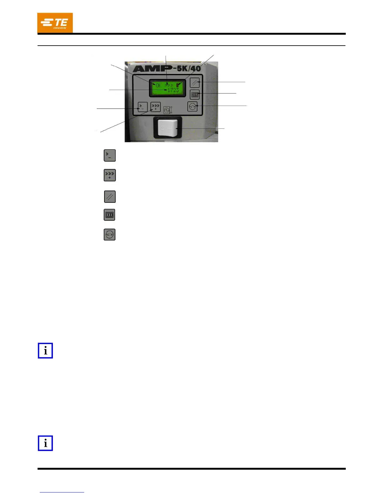
Machine
Status/
Error
Code
Decrease
Speed
--
Decrease
the
motor
speed
for
normal
cycle
operation
and
for
jogging.
Increase
Speed
--
Increase
the
motor
speed
for
normal
cycle
operation
and
for
jogging.
Error
Reset
--
Clears
the
displayed
error
code.
Count
Reset
--
Clears
the
batch
count
to
0.
Jog
--
Causes
the
DC
motor
to
rotate
at
the
jog
speed
set
by
the
Increase
/
Decrease
Speed.
Speed
Indication
-
-
Each
“>”
represents
a
portion
of
the
full
operation
or
jog
speed
setting.
Minimum
speed
is
denoted
with
a
single
“>.
Maximum
speed
is
denoted
by
“>>>>>>.”
Machine
Status
/
Error
Code
Display
--
Displays
“OK”
if
there
is
no
error
code
being
displayed
or
“ERRxxx”
when
an
error
has
occurred.
The
“xxx”
represents
a
number
corresponding
to
an
error
described
in
the
error
code
table
(Figure
17).
Guard
Status
Indication
--
A
solid
“
"
indicates
that
the
guard
interlock
is
closed.
An
open
icon
in
this
display
indicates
that
the
guard
interlock
is
open.
The
DC
motor
will
not
run
when
the
guard
interlock
is
open.