06/29/17 ICA-202D OPERATION AND INSTALLATION MANUAL Page 30 of 32
Intercom with Recording and Paging
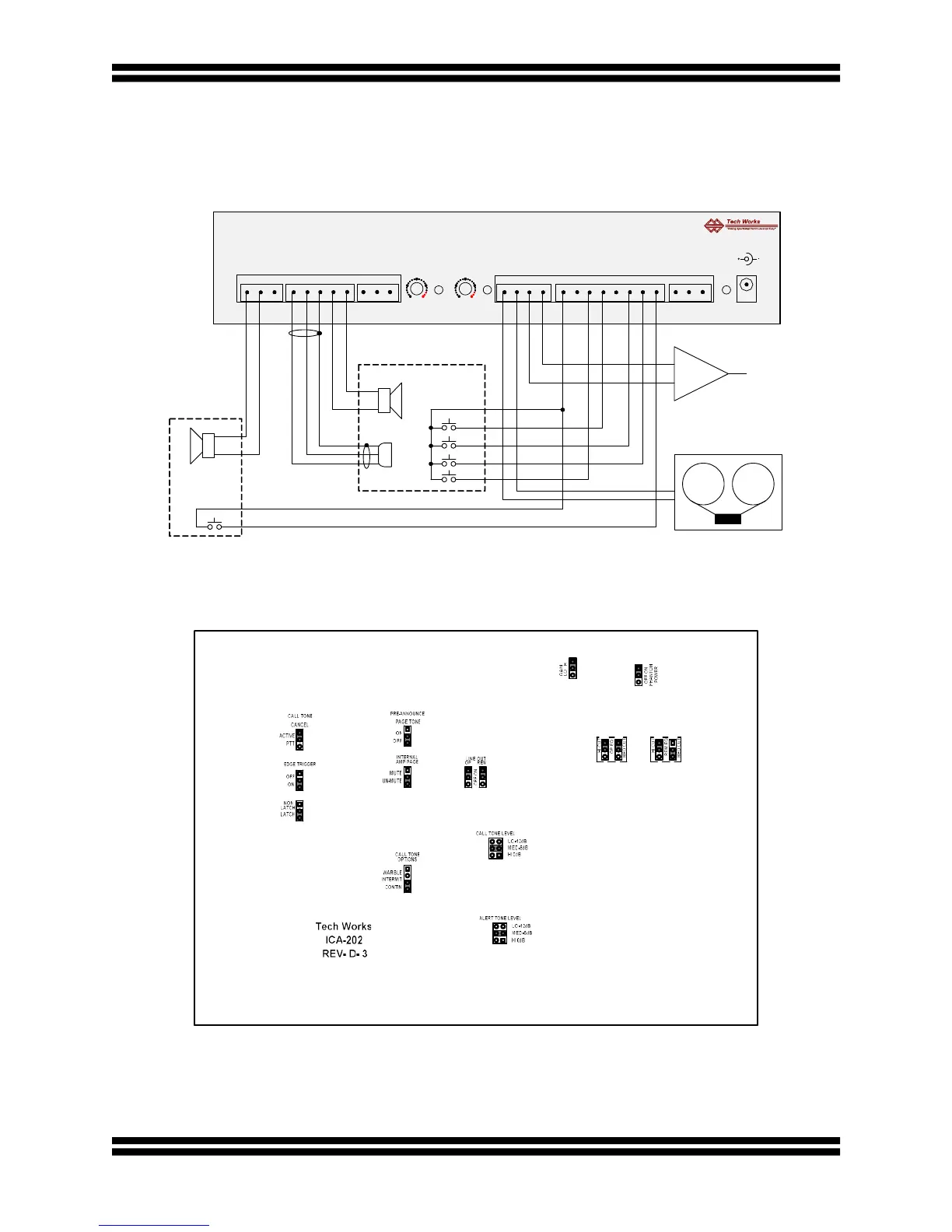
Below is a basic wiring diagram for intercom with a logging recorder and external paging
amplifer.
Below are the internal jumper settings.
As shown, both the Operator, and Remote are Recorded. Many other configurations are
available by combining this application with applications such as PLC control and others.
OP MIC (-)
REM SPKR (+)
REM SPKR (-)
OP MIC (+)
OP SPKR (-)
COMMON
OP SPKR (+)
COMMON
PAGE OUT (-)
PAGE OUT (+)
24VDC-2A
P-TONE SW
PTT SW
PAGE SW
ACTIVATE SW
MUTE SW
SHUT OFF SW
CHASSIS
+24VDC
COMMON
ICA-202D
Tech Works * YORBA LINDA * CA * 1-800-813-1080 * WWW.TECH4PEOPLE.COM
CALL SW
OP EXT DN
COMMON
OP EXT UP
COMMON
LINE OUT (+)
LINE OUT (-)
OPERATOR
LEVEL
ACTIVE
ACTIVE
LEVEL
REMOTE
POWER
TALK
ON
OFF
OPERATOR
REMOTE
LOGGING RECORDER
PAGE
PA-402
EXTERNAL
PAGING
AMPLIFIER
CALL


 To Next Page