
В
ВладимирMay 27, 2025
Под каким номером techem Vario 4 Тип 4.5.1 зарегистрирован Государственном реестре СИ "АРШИН" ? Спасибо.
Под каким номером techem Vario 4 Тип 4.5.1 зарегистрирован Государственном реестре СИ "АРШИН" ? Спасибо.
Identifies qualified craftsmen and specialist personnel trained by Techem.
Describes the meter's exclusive use for physically correct data collection of energy consumption in cooling systems.
Outlines regulations, earthing, lightning protection, cable distance, and cleaning guidelines for safe operation.
Details the non-replaceable lithium battery designed for the meter's service life.
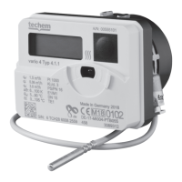
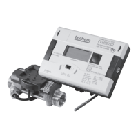
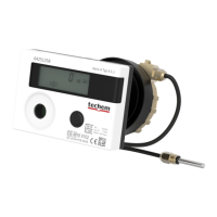
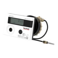
Lists PTB compliance, geometry variants, detachable unit, fixed cables, sensors, and flow direction recognition.
Covers selection of energy unit (kWh/GJ) and installation location (inlet/outlet) during initial setup.
Specifies temperature measurement and medium temperature ranges for the meter's operation.
Defines the permissible ambient temperature range for the device's operation.
Details transmission frequency and rating if the radio function is enabled for the meter.
Specifies the cycle time for output measurements, such as 32 seconds.
Provides essential guidelines for proper installation, environmental compliance, and component placement.
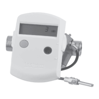
Illustrates the permitted orientations for installing the measuring capsule cooling meter.
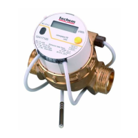
Provides a step-by-step guide for installing the TE1 geometry variant of the meter.
Details the procedure for installing temperature sensors, emphasizing placement and immersion.
Outlines the steps to perform a functional check after installation, including opening valves and checking the display.
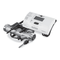
Details how to detach and mount the computer unit separately from the volume measuring section.
Covers applying seals and insulating all components after installation for finalization.
Explains error codes, their priorities, and how errors are displayed on the device.
Provides initial checks for system operation, shut-off devices, and pipe condition before meter troubleshooting.
Specific steps to resolve error F-6 related to flow direction recognition, including meter replacement if persistent.
Explains how the display switches off, updates, and how to navigate between 4 display levels using button presses.
Details the specific readout and service levels, including their corresponding codes and meanings.
Details the display levels for showing maximum recorded values for output and flow rates.
Explains how to access test modes and parameterize device properties like energy unit and installation location.
| Brand | techem |
|---|---|
| Model | Vario 4 Typ 4.5.1 |
| Category | Measuring Instruments |
| Language | English |