Do you have a question about the Technics SL-P350 and is the answer not in the manual?
Details on audio output, frequency response, S/N ratio, and harmonic distortion.
Dimensions, battery type, and requirements for the remote control unit.
Power supply voltage, power consumption, physical dimensions, and unit weight.
Lists all accessories included with the SL-P350 compact disc player.
Identifies caution labels related to laser radiation and product warnings.
Instructions for securing the optical pickup during transport to prevent damage.
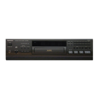
Identifies and explains the function of each button on the player's front panel.
Explains the meaning and function of various display indicators on the unit.
Lists the functions and buttons of the remote control unit for operating the player.
Shows how to connect the player to amplifiers and other audio equipment.
Procedures for safely handling the sensitive optical pickup component to prevent damage.
Methods to prevent electrostatic discharge damage to the optical pickup.
Step-by-step guide to remove the outer casing and front panel of the unit.
Instructions for removing internal circuit boards and the power transformer.
Procedure for removing the spindle motor assembly for maintenance.
Identifies key adjustment points on the main PCB for calibration purposes.
Details how to connect the servo gain adjuster tool for calibration tasks.
Procedure to adjust the RF signal eye pattern for optimal playback performance.
Procedure to adjust the focus error signal for proper disc tracking.
Procedure to adjust the tracking error signal for accurate disc following.
Steps to adjust the Phase Locked Loop for signal synchronization.
Lists pin functions for the MN6622 Digital Signal Processing LSI.
Illustrates the components and method for packing the unit for shipment or storage.
Exploded diagrams showing the main external and chassis components of the player.
Lists part numbers and descriptions for electronic components used in the unit.
Lists part numbers for mechanical components, cabinets, and accessories.
Diagram showing component placement and routing on the main circuit board.
Diagrams showing component placement on operation and power source circuit boards.
Provides pinout and function details for various ICs and diodes.
Shows the internal wiring and grid connection diagram for the FL display.
Detailed electronic schematics for the remote control unit, power supply, and main circuits.
Illustrates the overall functional blocks and signal flow of the player.