EasyManua.ls Logo

Technics SL-P999

Technics SL-P999
47 pages
To Next Page IconTo Next Page
Loading...
ORDER
NO.
AD8812312C9
Service
Manual
aise
[DIGITAL_|
DIGITAL
AUDIO
SPECIFICATIONS
i
Audio:
No.
of
channels
2
channel
(stereo)
Output
voltage
2.5Vrms
Frequency
response
2~20,000
Hz+0.3dB
Dynamic
range
100dB
SIN
ratio
113dB
Total
harmonic
distortion
0.0023%
Harmonic
distortion
0.0013%
Channel
separation
110dB
Digital
filter
20-bit
realizing
high
resolution
output
8
times
oversampling
DA
converter
4
DAC
system
Output
impedance
600Q
Digital
output
optical
Realizing
resolution
output
20-bit
@
Signal
format
Sampling
frequency
44.1kHz
Error
correction
Technics
New
Super
Decoding
Algorithm
(8
Samples
Linear
Interpolation)
e
Matsushita
Electric
Industrial
Co.,
Ltd.
ec
nics
Central
P.O.
Box
288,
Osaka
530-91,
Japan
Compact
Disc
Player
oL-P999
Color
(K)...
Black
Type
Area
Code
olor
|
Continenta
Europe,
|
[6
[unites
kingdom.
|_|
w
eas
(XA)
Asia,
Latin
America,
Middle
Near
East,
al
|
|
Lm
|
Africa
and
Oceania.
(PA)
Far
East
PX.
(PE)
European
Military.
(PC)
European
Audio
Club.
@Pickup
Type
Aspherical
Surface
Glass
Press
Lens
Fine
focus
1
beam
Beam
source
Semiconductor
laser
Wave
length
780nm
@
Traverse
unit
Type
High
speed
linear
motor
@
General
Power
supply
For
Continental
Europe
AC
50/60
Hz,
220V
For
United
kingdom
AC
50/60Hz,
110V/127V/220V/240V
For
Australia
AC
50/60Hz,
240V
For
others
AC
50/60
Hz,
110V/127
V/220V/240V
Power
consumption
16W
Headphones
output
level
60
mW/32Q
Dimensions
(W
x
H
x
D)
430
x
126.5
x
338mm
Weight
6kg
Specifications
subject
to
change
without
notice.
Weight
and
dimensions
shown
are
approximately.
Panasonic
Tokyo
Sales
Department
Matsushita
Electric
Industrial
Co.,
Ltd.
World
Trade
Center
Bldg.,
4-1,
Hamamatsu-cho,
2-chome,
Minato-ku,
Tokyo
105,
Japan

Other manuals for Technics SL-P999

Question and Answer IconNeed help?

Do you have a question about the Technics SL-P999 and is the answer not in the manual?

Technics SL-P999 Specifications

General IconGeneral
TypeCD Player
Disc formatCD
Frequency Response2 Hz - 20 kHz
Output Level/Voltage2.0 V
Digital outputsCoaxial, Optical
Channel Separation110 dB
Dynamic Range100 dB
Dimensions (W x H x D)430 x 116 x 300 mm
Digital converterMASH (Multi-stage noise shaping)

Summary

SPECIFICATIONS

Audio Specifications

Detailed technical specifications for audio output and performance.

Pickup Specifications

Technical details regarding the optical pickup system and laser.

Signal Format

Information on the digital signal format and error correction used.

PLACEMENT

Before Placement Procedures

Steps to prepare the player for use by releasing the optical pickup lock.

Placement Notes and Precautions

Guidelines for optimal placement to ensure performance and avoid issues.

ACCESSORIES

LASER DIODE PRECAUTIONS

Cautionary Labels and Warnings

Safety instructions and warnings related to the laser diode component.

CONNECTIONS

REMOTE CONTROL TRANSMITTER

Operation Notes

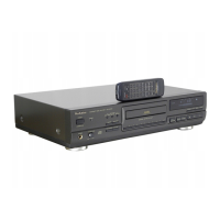
Guidelines for effective use of the remote control transmitter.

LOCATION OF CONTROLS

Control Section Overview

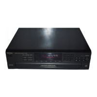
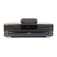
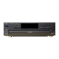
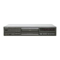
Identification and function of the main control buttons on the unit.

Indicators and Operation Status

Explanation of unit displays and indicators during operation.

Remote Control Transmitter Controls

Mapping of remote control buttons to unit functions.

BASIC OPERATION

Playback Modes: Auto, Direct Access, Random

How to use Auto, Direct Access, and Random play functions.

Display Mode Options

Changing how playback time and position are displayed.

OPTICAL PICKUP HANDLING

Static Electricity and Grounding Precautions

Steps to prevent damage from static discharge and ensure grounding.

DISASSEMBLY INSTRUCTIONS

Cabinet, Clamper, Front Panel, Disc Holder Removal

Procedures for removing external and internal cabinet components.

PCB and Component Removal Procedures

Steps to remove various circuit boards and other internal components.

MEASUREMENTS AND ADJUSTMENTS

Preparation and Tools

Required preparations and special tools for measurements and adjustments.

Adjustment Points Overview

Identification of key adjustment points on the Servo and Main PCBs.

MEASUREMENTS AND ADJUSTMENTS (continued)

Measuring Instruments and Special Tools

List of necessary measuring instruments and test discs for adjustments.

Turntable Height and Mechanical Adjustments

Procedures for adjusting turntable height and mechanical alignment.

MEASUREMENTS AND ADJUSTMENTS (continued)

Optical Pickup Alignment Adjustments

Steps for adjusting Best Eye, Focus Gain, and Tracking Gain.

Advanced Adjustment and Playback Checks

Procedures for Focus Offset, Tracking Offset, Balance, and playback verification.

MEASUREMENTS AND ADJUSTMENTS (continued)

DA Converter Circuit Adjustments

Procedures for adjusting distortion, DAC gain, and offset voltage.

TERMINAL GUIDE

IC Terminal Identification

Pinout and function of integrated circuits used in the player.

Transistor and Diode Identification

Identification and function of transistors and diodes.

INTERNAL CONNECTION DIAGRAMS

FL Display Grid Connection

Visual representation of the FL display grid connections.

FL Display Anode Connection Table

Table mapping grid segments to anode control signals.

BLOCK DIAGRAM

PRINTED CIRCUIT BOARD LAYOUTS

Operation, Headphones, MotorSwitch PCB Layouts

Component placement diagrams for operation, headphones, and motor/switch boards.

PRINTED CIRCUIT BOARD LAYOUTS (continued)

Servo PCB Layout

Component placement diagram for the servo circuit board.

PRINTED CIRCUIT BOARD LAYOUTS (continued)

Main, Disc Illuminator, Search, Extension PCB Layouts

Component placement diagrams for main and auxiliary circuit boards.

PRINTED CIRCUIT BOARD LAYOUTS (continued)

Power Supply PCB Layout

Component placement diagram for the power supply circuit board.

TROUBLESHOOTING GUIDE

Play Operation Sequence Check

Flowchart for diagnosing playback issues based on operational sequence.

TOC Read to Playback Troubleshooting

Flowchart for diagnosing issues during TOC reading and playback.

PACKING PROCEDURES

REPLACEMENT PARTS LIST

EXPLODED VIEWS

Remote Control Unit Parts

Diagram showing the disassembled parts of the remote control unit.

EXPLODED VIEWS (continued)

Cabinet and Chassis Parts

Exploded view of the player's main chassis and cabinet components.

EXPLODED VIEWS (continued)

Traverse Deck Parts

Exploded view of the CD player's traverse deck mechanism.

Related product manuals