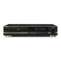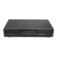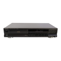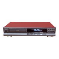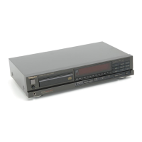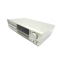
Do you have a question about the Technics SL-PG520A and is the answer not in the manual?
Details about audio playback specifications like channels, frequency response, output voltage, and impedance.
Specifications related to the optical pickup unit, specifically wavelength.
General specifications including power supply, dimensions, and weight.
Instructions for releasing transport security devices before using the player.
Guidelines for choosing a suitable location to avoid damage and interference.
Methods for cleaning the optical lens using a blower and lens cleaner solution.
Warnings and guidelines regarding laser diode safety, handling, and viewing.
Detailed explanation of the player's control buttons and their functions.
Explanation of the various indicators displayed on the player unit.
Functions of buttons on the remote control transmitter, mirroring unit controls.
Step-by-step guide to remove the main external cabinet of the player unit.
Procedure for detaching the front panel assembly from the player.
Instructions for removing the printed circuit board for the headphone section.
Steps to remove the printed circuit board associated with the power switch.
Guide to detach the operation and search printed circuit boards.
Procedure for removing the primary main printed circuit board from the unit.
Steps for removing the lid that covers the disc compartment.
Method for inspecting the main printed circuit board and its components.
Steps to remove the disc holder retaining mechanism components.
Procedure for detaching the component that holds the CD.
Guide for removing the entire disc loading mechanism.
Instructions for removing the servo control printed circuit board.
Steps to detach the motor responsible for loading the disc tray.
Procedure for detaching the laser assembly and optical pickup.
Steps for removing the printed circuit board that provides power to the unit.
Steps to check the servo printed circuit board after disassembly.
Steps to prepare the unit for measurements and adjustments.
Identification of specific points on the servo PCB for adjustment.
Procedure for adjusting the laser power output level using a VR.
Procedure for adjusting the focus offset using a VR and oscilloscope.
Verification steps for skip search, manual search, and playability after adjustments.
Detailed pin functions for the TDA8808T photo diode signal processor IC.
Detailed pin functions for the TDA8809T radial error signal processor IC.
Detailed pin functions for the MN6626 digital signal processor IC.
Detailed pin functions for the MN1871617PMC system control and FL drive IC.
Detailed pin functions for the MN6474 digital filter and D/A converter IC.
Diagram illustrating the grid connections for the FL display.
Table detailing anode connections for the FL display components.
Comprehensive list of terminal functions for integrated circuits, transistors, and diodes.
Diagram showing the layout and component placement of the servo printed circuit board.
Diagram illustrating the layout and component placement of the operation printed circuit board.
Diagram showing the layout and component placement of the search printed circuit board.
Diagram illustrating the layout and component placement of the power switch printed circuit board.
Diagram showing the layout and component placement of the main printed circuit board.
Diagram illustrating the layout and component placement of the power supply printed circuit board.
Diagram showing the layout and component placement of the headphones printed circuit board.
List of replacement integrated circuits with part numbers and descriptions.
List of replacement transistors with part numbers and descriptions.
List of replacement diodes with part numbers and descriptions.
List of replacement variable resistors and switches with part numbers.
List of replacement connectors, jacks, and flat cables with part numbers.
List of replacement earth contact components with part numbers.
List of replacement parts for the cabinet, chassis, and loading unit.
List of replacement packing materials and accessories like power cords and manuals.
Diagram showing the exploded assembly of cabinet and chassis parts.
Diagram showing the exploded assembly of the loading unit components.
Guidelines for grounding to prevent electrostatic damage during handling.
Detailed list of resistors and capacitors with their values and remarks.
Flowchart outlining the player's operation sequence and troubleshooting steps.
Flowcharts detailing troubleshooting for power-on and TOC read sequences.
Flowcharts for diagnosing issues with servo lock, RF signal, and audio output.
