EasyManua.ls Logo

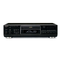
Technics SL-PS670D

Technics SL-PS670D
34 pages
To Next Page IconTo Next Page
To Previous Page IconTo Previous Page
Loading...
C731
6.3V220
=
MN6627I3RG1
.
SERVO
PROCESSOR/DIGITAL
=—MCLK()
SIGNAL
PROCESSOR/DIGITAL
moata
@)
FILTER
&
D/A
CONVERTER
~
SV
|
SL-PS670A SL-PS670A
|
cN702
Lch
OUT
A.GND
T=25mS
\
>
r
Sv
PLAY
~
5
roa
mmoow
@)
TRCRS
@)
©)
OV
OV)
4.9V
(4.8V)OV
12.3V)4.9V
He
735
Z0.022
[_erss
xe
FGABCDEFGHI
C743
Z0022
ma
2=
t3v
|p-p
2mS.0.1V/DIV.
A
pd
ley
TX
TPIG
TPI4
c
TPI3
°
D
TPI2
°
E
TPII
°
ia
TPIO
9
TPS
°
TPS
°
TPT
°
3/2
al<
ae
obeebed
$
Rech
OUT
+B(2)
D.GND
BCLK
(6)
+B
(1)
P.GND
MCLK
MDATA
MLD
SENSE
/
FLOCK
/TLOCK
LRCK
SQCK
SUBQ
©
SRDATA
STAT
/RST
TPI
(2)
VCoF
ool
REST
Sw
11
12
13
@
This
schematic
diagram
may
be
modified
at
any
time
with
the
development
of
new
technology.
Notes:
@
S601
:
Numeric
(8)
switch
®
S602
:
Numeric
(3)
switch
@
S603
:
Recall
switch
(RECALL)
e@
S604
:
F.
Skip
switch
(
bp]
)
e
S605
:
Stop
switch
(
Hf
)
@
S606
:
Numeric
(9)
switch
@
S607
:
Numeric
(4)
switch
©
S608
:
Random
play
switch
(RANDOM)
@
S609
:
R.
Skip
switch
(
kd<)
@
S610
:
Pause
switch
(J
})
@
S611
:
Numeric
(0)
switch
@
S612
:
Numeric
(5)
switch
©
S613
:
Repeat
switch
(REPEAT)
e@
S614
:
R.
Search
switch
(<<
)
@S615
:
F.
Search
switch
(
pp
)
@
S616
:
Numeric
(6)
switch
@
S617
:
Numeric
(1)
switch
©
S618
:
Program
switch
(PROGRAM)
@
S619
:
Time
fade
switch
(TIME
FADE)
e@
S620
:
Auto
cue
switch
(AUTO
CUE)
®
S621
:
Numeric
(7)
switch
®
S622
:
Numeric
(2)
switch
®
S623
:
Clear
switch
(CLEAR)
@
S624
:
Tape-side
select
switch
(SIDE
A/B)
e@
S625
:
Time
mode
select
switch
(TIME
MODE)
@
S626
:
Disc
tray
open/close
switch
(4
OPEN/CLOSE)
®
S627
:
Numeric
(210)
switch
@
S628
:
Play
switch
(
B>
)
@
S629
:
Edit
tape
length
switch
(TAPE
LENGTH)
@
S630
:
Peak
level
search
switch
(PEAK
SEARCH)
@
S651
:
Power
“STANDBY
(I)
/ON”
switch
(POWER)
@
S701
:
Reset
switch
@S781
:
Disc
tray
open
detection
switch
@
S782
:
Disc
tray
close
detection
switch
@
Indicated
voltage
values
are
the
standard
values
for
the
unit
measured
by
the
DC
electronic
circuit
tester
(high-
impedance)
with
the
chassis
taken
as
standard.
Therefore,
there
may
exist
some
errors
in
the
voltage
values,
depending
on
the
internal
impedance
of
the
DC
circuit
tester.
No
mark:
CD
STOP
(
)
:
CD
PLAY
[1kHz,
L
+
R,
0
GB]
@
Important
safety
notice:
Components
identified
by
A
mark
have
special
characteristics
important
for
safety.
Furthermore,
special
parts
which
have
purposes
of
fire-retardant
(resistors),
high-quality
sound
(capacitors),
low-
noise
(resistors),
etc.
are
used.
When
replacing
any
of
components,
be
sure
to
use
only
manufacturer's
specified
parts
shown
in
the
parts
list.
©
Caution!
IC
and
LSI
are
sensitive
to
static
electricity.
Secondary
trouble
can
be
prevented
by
taking
care
during
repair.
Cover
the
parts
boxes
made
of
plastics
with
aluminum
foil.
Ground
the
soldering
iron.
Put
a
conductive
mat
on
the
work
table.
Do
not
touch
the
legs
of
IC
or
LSI
with
the
fingers
directly.
®
Voltage
and
signal
line
amuaap=====
:
Positive
voltage
line
aua=>===e
:
Negative
voltage
line
:
CD
signal
Line
®
The
supply
part
number
is
described
alone
in
the
replacement
parts
list.
Production
Part
No.
Supply
Part
No.
1C11
LM2940T5M
LM2940T5
—~18-

Related product manuals