Do you have a question about the Technics SL-PS900 and is the answer not in the manual?
Details audio performance metrics and pickup wavelength.
Covers power consumption, power supply, dimensions, and weight.
Maps country codes to specific color designations for the unit.
Instructions for initial setup, voltage adjustment, and safe transportation.
Lists all accessories provided with the CD player, such as cables and batteries.
Details crucial safety warnings regarding laser diode exposure and caution labels.
Guidance on unit placement and connecting external audio equipment.
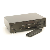
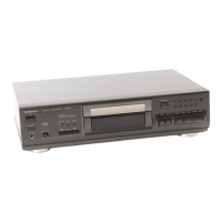
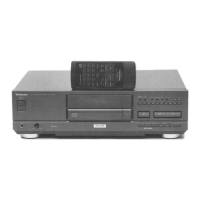
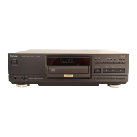
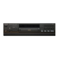
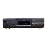
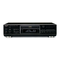
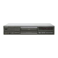
Identifies and describes the functions of front panel buttons and indicators.
Details the meaning of various indicators shown on the player's display.
Describes the functions of all buttons on the remote control.
Guidance for handling the optical pickup and applying traverse oil.
Steps for removing external parts and initial circuit boards.
Procedures for removing main PCBs, power supply, and loading mechanisms.
Steps for disassembling drive mechanism parts like the yoke and tray.
Instructions for removing the motor assembly and associated switch PCBs.
Procedures for optical pickup removal and checking main/servo PCBs.
Outlines preparation, adjustment points, and procedures for turntable and mechanical adjustments.
Lists pin functions for the AN8800SCE2 servo amplifier IC.
Details best eye adjustment and verification of playback operations.
Lists pin functions for the MN6626 digital signal processor IC.
Lists pin functions for the MN6650 digital servo processor IC.
Details pin functions for the MND1616PKP system control IC.
Lists pin functions for the X24LC01P E² PROM IC.
Details pin functions for the MN1554PKK6 system control IC.
Lists pin functions for the MN6474 digital filter and D/A converter IC.
Details pin functions for the AN8377N traverse motor drive IC.
Compares servo systems and outlines the automatic adjustment sequence.
Step-by-step guide for diagnosing and resolving CD playback issues.
Illustrates internal connections and wiring for the FL display unit.
Visual representation of the player's internal system architecture and component interactions.
Provides a reference guide for the terminal functions of various electronic components.
Detailed schematic of the optical pickup and servo amplifier circuitry.
Visual layouts for the servo, FL drive, and main printed circuit boards.
Illustrates how various PCBs and components are wired together.
Diagrams showing the exploded view of the player's cabinet and chassis components.
Detailed exploded view of the traverse deck mechanism parts.
Lists materials for packing and all included accessories.
Lists part numbers for integrated circuits, transistors, and diodes.
Lists part numbers for switches, coils, connectors, and jumpers.
Details part numbers and values for resistors and capacitors.
Lists capacitor values and remarks, plus other small components.
Details changes in part numbers for the FL drive and main PCB.
Shows updated schematic for the FL drive circuit, including additions.
Illustrates updated schematic for the main circuit, including additions.