EasyManuals Logo

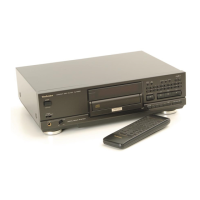
Technics SL-PS900 Service Manual

Technics SL-PS900
44 pages
To Next Page IconTo Next Page
To Previous Page IconTo Previous Page
Page #13 background imageLoading...
Page #13 background image
oe
Removal
of
the
optical
pickup
Procedure
4-29-10
|
1:
Remove
the
3
screws
(O~®).
342-1314
|
2:
Unsolder
the
2
terminals
of
spindle
1516-19
motor.
3.
Remove
the
FPC
board
from
the
optical
pickup.
Connector
(CNIO!)
Sree
(1)
Caution:
To
prevent
the
breakdown
of
the
laser
diode,
antistatic
shorting
pin
is
inserted
into
the
FPC
board.
FPC
board
Shorting
pin
Ref.
No.
21
Procedure
1-2--9-10
12-13-14
15-16-19
—21
Removal
of
the
spindle
motor
1.
Loosen
the
screw
(@)
by
using
a
1.27mm
allen
wrench
and
remove
the
turntable.
2.
Remove
the
2
screws
(Q, ©).
Caution:
1.
Turntable
height
adjustment
is
necessary
any
time
the
turntable
or
spindle
motor
is
replaced.
2.
The
(+)-terminal
of
the
spindle
motor
is
indicated
by
the
red
mark.
'
Adjustment
of.
turntable
height
1.
Insert
a
0:9mm
clearance
gauge
(RZZ0297)
between
the
turntable
and
loading
base
as
shown
in
the
figure.
2.
Tighten
the
turntable
set-screw
by
using
a
1.27mm
allen
wrench.
Caution:
Refer
to
turntable
height
adjustment
(See
page
16).
aia
e
Removal
of
the
optical
pickup
Procedure
1-29-10
12-13-14
—15—16-19
Unsolder
the
20
terminals
Brush
terminal
Optical
pickup
1.
Remove
the
2
screws
(QO,
@).
2.
Unsolder
the
2
terminals
and
the
2
screws
(@,
©).
Caution:
Take
care
not
to
touch
the
brush
terminal.
Refer
to
the
handling
precautions
for
optical
pickup
and
instructions
for
traverse
oil
(See
page
8).
Turn
table
0.9mm
clearance
gauge
peerereten
0.9
mm
(RZZ0297)
Spindle
motor
ah
“NO
1
Procedure
1-2-9-10
11-1214
—15—23
Remove
the
7
screws
(Q~@).
Yoke,
magnet
&
clamper
Test
disc
.
Attach
the
front
panel
ass’y
to
the
unit.
.
Rotate
the
pulley
gear
in
the
direction
of
arrow
until
the
traverse
unit
comes
up.
.
Place
the
test
disc
and
secure
it
by
using
the
yoke,
magnet
and
clamper.
.
Power
switch
toON.
.
While
pushing
the
open/close
det.
switch
($751)
in
the
direction
of
arrow,
push
the
play
switch.
.
When
checking
the
soldered
surface
of
servo
P.C.B.
and
replacing
the
parts,
do
as
shown.
|
SL-PS900
eWhen
checking
the
soldered
surface
of
the
main
P.C.B.
and
replacing
the
parts,
do
as
shown
below.
Cautions:
1.
Connect
the
main
P.C.B.
ground
terminal
(LINE
OUT
terminal)
to
the
chassis
with
a
lead
wire.
2.
Connect
the
operation
P.C.B.
ground
terminal
to
the
chassis
with
a
lead
wire.
Operation
P.C.B.
4.
Connect
the
3
flat
cables
(CN401,
CN40?,
CON403).
5.
Fix
the
loading
unit
by
tape.
Power
switch

Questions and Answers:

Question and Answer IconNeed help?

Do you have a question about the Technics SL-PS900 and is the answer not in the manual?

Technics SL-PS900 Specifications

General IconGeneral
BrandTechnics
ModelSL-PS900
CategoryCD Player
LanguageEnglish

Related product manuals