Do you have a question about the Technics SL-PG490 and is the answer not in the manual?
Technical specifications for audio performance parameters.
Technical specifications for general parameters like power and dimensions.
Technical specifications related to the optical pickup unit.
Precautions for handling the optical pickup to prevent electrostatic damage.
Procedures for grounding to prevent electrostatic discharge during servicing.
Diagram and instructions for analog audio connections.
Diagram and instructions for digital audio connections.
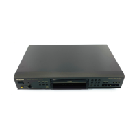
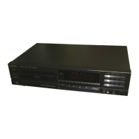
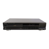
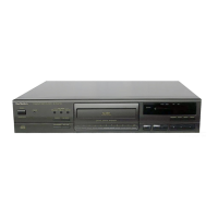
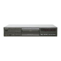
Identification and function of controls on the main unit.
Identification and function of buttons on the remote control.
Steps for checking the operation of various PCBs.
Procedures for replacing major components of the unit.
Procedure for performing self-diagnosis on the servo system.
Schematic diagram for the CD servo control circuit.
Schematic diagram for the power switch control circuit.
Schematic diagram for the operation control circuit.
Schematic diagram for the loading motor control circuit.
Schematic diagram for the main control circuit.
Schematic diagram for the headphone amplification circuit.
Physical layout of the CD servo printed circuit board.
Physical layout of the power switch printed circuit board.
Physical layout of the loading motor printed circuit board.
Physical layout of the operation printed circuit board.
Physical layout of the main printed circuit board.
Detailed pin functions for the UPD78042A014 IC.
Detailed pin functions for the AN8805SBE1 IC.
Detailed pin functions for the MN662713RG1 IC.
Detailed pin functions for the MN662713RG1 IC.
Detailed pin functions for the AN8389SE1 IC.
| Type | CD Player |
|---|---|
| Disc Format | CD, CD-R, CD-RW |
| Frequency Response | 2 Hz to 20 kHz |
| Dynamic Range | 96 dB |
| Channels | 2 (Stereo) |
| Digital Output | Optical |
| Digital Converter | 1-bit DAC |
| Line Output | 2V (at 0 dB) |