EasyManua.ls Logo

Technics SU-C1010

Technics SU-C1010
42 pages
To Next Page IconTo Next Page
Loading...

Other manuals for Technics SU-C1010

Question and Answer IconNeed help?

Do you have a question about the Technics SU-C1010 and is the answer not in the manual?

Technics SU-C1010 Specifications

General IconGeneral
BrandTechnics
ModelSU-C1010
CategoryAmplifier
LanguageEnglish

Summary

Product Specifications

Input Sensitivity, Distortion, and Frequency

Details input sensitivity, distortion, S/N, and frequency response.

Phono and Tone Control Specifications

Specifies phono input voltage and tone control ranges.

Safety Warnings

Electrical Hazard and Servicing Caution

Warns about electrical shock risks and servicing protocols.

AC Mains Lead Safety (UK)

Fuse Replacement and Wiring

Instructions for fuse replacement and mains lead wiring.

Front Panel Controls

Power, Input Selection, and Indicators

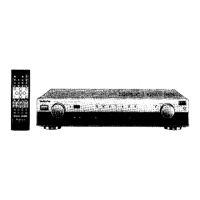
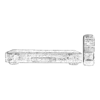
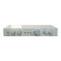
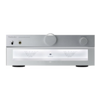
Explains power, input selection, and status indicators.

Inserting the Rechargeable Battery

Battery Installation Procedure

Step-by-step guide for inserting the rechargeable battery.

Connecting to Power Amplifiers

PRE OUT and Equalizer Connections

Guides for connecting to power amps and graphic equalizers.

Connecting a DVD Player

DVD Connection Types

Instructions for 6-channel and 2-channel DVD player connections.

Power Supply and Battery Recharging

Initial Battery Recharging Process

Explains the initial charging cycle for the rechargeable battery.

Using Battery Power

Battery Operation and Switching

Guides on operating the unit on battery and switching sources.

Checking Battery Status

Indicator Lamp Meanings

Explains the status indicated by the 'LEVEL' and 'CHARGE' lamps.

Listening Operation

Preparation and Source Selection

Steps for preparing the unit and selecting audio sources.

Sound Adjustment Features

Balance, Tone Control, and VGCA

Adjusting sound balance, tone quality, and VGCA circuit functions.

Operation Checks and Component Replacement

Checking Main P.C.B. and Removing Boards

Procedures for inspecting and removing internal circuit boards.

Schematic Diagram Notes

Safety Notices and Component Replacement

Important safety warnings and guidelines for component replacement.

Schematic Diagrams (Main & PRE OUT Circuits)

Main Printed Circuit Board Diagram

System Block Diagram

Wiring Connection Diagram

Measurement and Adjustment Procedures

Output Voltage Adjustment Procedure

Detailed steps to adjust the output voltage.

Terminal Functions of ICs

IC701 (Micro Computer) Pin Functions

Pinout and function details for the M38503M2404F microcomputer.

Replacement Parts List

Cabinet Parts Location

Packaging Instructions

Related product manuals