Do you have a question about the Technics SU-CH700 and is the answer not in the manual?
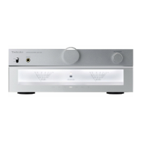
Details power output and distortion characteristics of the power amplifier.
Covers input sensitivity, impedance, and loudness features of the pre-amplifier.
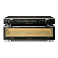
Outlines power consumption, supply voltage, dimensions, and weight of the unit.
Explains the function of protection circuitry and troubleshooting steps.
Lists all included accessories with part numbers and quantities.
Illustrates connections for video decks, players, DAT, TV, and speakers.
Explains how to connect and disconnect flat cables between system components.
Step-by-step guide for setting the unit's internal clock accurately.
Instructions for removing the main unit cabinet.
Guide to removing the front panel assembly.
Steps to remove the Front Light (FL) Printed Circuit Board.
Procedure for removing the Mic and Headphone Jack PCBs.
Instructions for removing the Operation Printed Circuit Board.
Steps to remove the rear grill assembly.
Guide to removing AC input and input/output terminal PCBs.
Instructions for removing PCB support and power transformer units.
Steps for removing the fan and the main Printed Circuit Board.
Instructions for removing power IC and regulator transistors.
Guidance on checking the main Printed Circuit Board after installation.
Detailed steps for removing the fan motor assembly.
Critical safety warnings regarding static electricity and component handling.
Detailed schematic of the Front Light (FL) display circuitry.
Schematic of the unit's operation circuitry, including input selection and controls.
Circuit diagram for the headphone jack interface.
Schematic of the microphone input jack circuitry.
Schematic of the input/output terminal Printed Circuit Board.
Detailed circuit diagram of the unit's main amplifier section.
Continuation of the main amplifier circuit schematic.
Diagrams for power transformer (A) and (B) circuits.
Schematic for the AC input terminal connection.
Layout of the Front Light (FL) Printed Circuit Board.
Layout of the Operation Printed Circuit Board.
Layouts for Headphone and Mic Jack Printed Circuit Boards.
Layout of the Input/Output Terminal Printed Circuit Board.
Layout of the Main Printed Circuit Board.
Reference guide for terminal pinouts of various ICs, transistors, and diodes.
Schematics for AC input terminal and power transformer PCBs.
Maps grid positions to functions displayed on the FL panel.
Lists pin numbers and their corresponding connections for the FL panel.
Shows anode connection details for various FL panel segments.
Illustrates functional blocks like buffer amp, bass amp, power amp, and system control.
Pin-by-pin breakdown of IC601's functions and signal assignments.
List of all transistors used in the unit.
List of all diodes used in the unit.
Lists fuses, oscillators, transformers, and display tubes.
Table of resistors with part numbers, values, and wattage.
Table of capacitors with part numbers, values, and voltage ratings.
Details of all switches, including their type and function.
Listing of various connectors and jack types used in the system.
List of capacitors with smaller capacitance values and voltage ratings.
List of capacitors with larger capacitance values and voltage ratings.
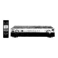
Visual guide showing where major internal and external parts are situated.
Catalog of all accessories provided with the unit, including cables, adapters, and antennas.
Details of packing materials used for system components.
Visual guide for packing individual system units and accessories.
| Frequency Response | 3 Hz to 80 kHz (+0 dB, -3 dB) |
|---|---|
| Total Harmonic Distortion | 0.1% (20Hz-20kHz, 8Ω, 50W) |
| Dimensions | 270 x 119 x 335 mm |
| Weight | 6.6 kg |
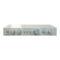
| Input sensitivity | 200 mV |
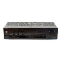
| Type | Stereo Integrated Amplifier |
| Output | Speakers |