Do you have a question about the Technics SU-X302 and is the answer not in the manual?
Electrical characteristics of the amplifier section, including power output and distortion.
Overall specifications of the unit, covering power consumption, supply, dimensions, and weight.
Explains the protection circuit function, conditions for activation, and reset procedure.
Lists accessories and their area-specific configurations, like power cords.
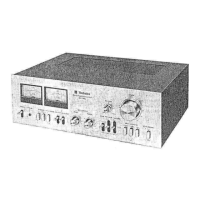
Describes how to adjust sound quality (Treble, Bass), balance, volume, and super bass.
Details how to connect external audio devices like cassette decks and other units.
Instructions for connecting main, surround speakers, and using the active current sensor.
Guidelines for AC outlet usage and connecting the AC power supply cord.
Procedures for removing the unit's casing, front panel, and switch circuit boards.
Procedure for removing the FL display driver circuit board.
Steps for removing operation controls, rear panel, and AC inlet PCB.
Steps for removing other PCBs and procedures for checking the main circuit board.
Instructions for removing key power supply components and replacing unit feet.
Diagrams for FL drive, operation switches, and various audio/control terminal circuits.
Diagrams for power supply, AC inlet/outlet, headphone sections, and voltage adjustment.
Visual layout of FL drive, operation switch, main, and terminal circuit boards.
Visual layout of AC power inlet/outlet and voltage adjustment circuit boards.
Pin configurations and functions for various integrated circuits, transistors, and diodes.
Detailed pin descriptions and functions for the M50754-180SP microcomputer IC.
| Type | Integrated Amplifier |
|---|---|
| Weight | 6.4 kg |
| Frequency Response | 3 Hz - 80 kHz |
| Total Harmonic Distortion | 0.05% |
| Signal-to-Noise Ratio | 100 dB |
| Inputs | Phono, CD, Tuner, Tape |
| Dimensions | 430 x 125 x 300 mm |
| Input sensitivity | 2.5 mV (Phono), 150 mV (Line) |
| Speaker load impedance | 8 - 16 Ohm |
| Signal to noise ratio | 100 dB (line) |