Do you have a question about the Technics SU-8055 X and is the answer not in the manual?
Detailed electrical characteristics and performance parameters of the amplifier section.
Overall specifications including power supply, dimensions, and weight.
Step-by-step guide for safely disassembling the unit's exterior panels.
Procedures for calibrating specific electronic settings and performance metrics.
Steps to set and balance DC voltage levels within the circuitry for optimal performance.
Detailed guide for safely removing and replacing the main power integrated circuit.
List of external and structural components available for replacement.
Inventory of fasteners and small hardware required for assembly and repair.
Components specifically related to the unit's packaging and shipping materials.
List of included or optional accessories provided with the unit.
List of integrated circuits used in the unit for replacement purposes.
List of transistors used in the unit for replacement purposes.
List of diodes used in the unit for replacement purposes.
List of coils and transformers used in the unit for replacement purposes.
| Power output | 55 watts per channel into 8Ω (stereo) |
|---|---|
| Input sensitivity | 2.5mV (MM), 150mV (line) |
| Output | 150mV (line) |
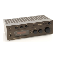
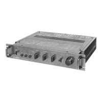
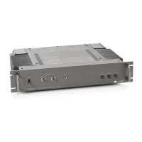
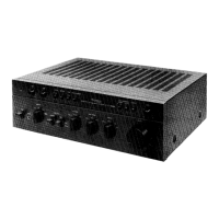
| Type | Stereo Integrated Amplifier |
| Speaker load impedance | 16Ω |