Do you have a question about the Technics SU-8600 and is the answer not in the manual?
Detailed specifications for the power amplifier stage, including output power, distortion, frequency response, and S/N ratio.
Specifications for the preamplifier stage, covering input sensitivity, impedance, and frequency response.
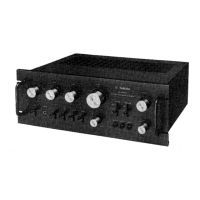
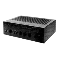
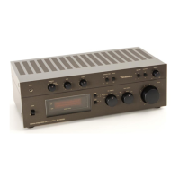
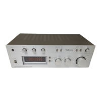
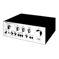
Identification of front panel controls, rear panel terminals, and internal component layout.
Schematic block diagram illustrating the integrated circuit SVITA7136P used in the amplifier.
Explanation of tone amplifier features and current mirror circuits for gain and stability.
Covers capacitor discharge safety warning and DC VTVM adjustment instructions.
Schematic showing the interconnections of various amplifier stages and signal paths.
Step-by-step guide for safely removing power transistors TR415 and TR416, including safety precautions.
Schematic diagrams of the power supply section, tailored for England [XE] and Scandinavia [XSD] & Swiss [XSW].
Diagram of the input circuit and equalizer amplifier board, showing component placement and connections.
Diagram of the tape monitor switch circuit board, illustrating component placement and connections.
Detailed schematic of the entire SU-8600 amplifier, showing all circuits and component interconnections.
Detailed block diagram showing switch functions and signal routing for various modes.
Important safety notice regarding shaded areas in the schematic, emphasizing the use of specified parts for safety.
Component layouts for amplifier sections, tone control, and power supply.
Component layout for volume control, speaker terminals, power indicator, and other controls.
List of replacement resistors, integrated circuits, transistors, and diodes with part numbers and specifications.
Diagram showing the physical location of various chassis components and parts.
List of replacement capacitors, fuses, switches, terminals, and component combinations.
List of replacement cabinet and chassis parts, including handles, knobs, and screws.
Information on packing materials, accessories, and regional variations for the SU-8600.